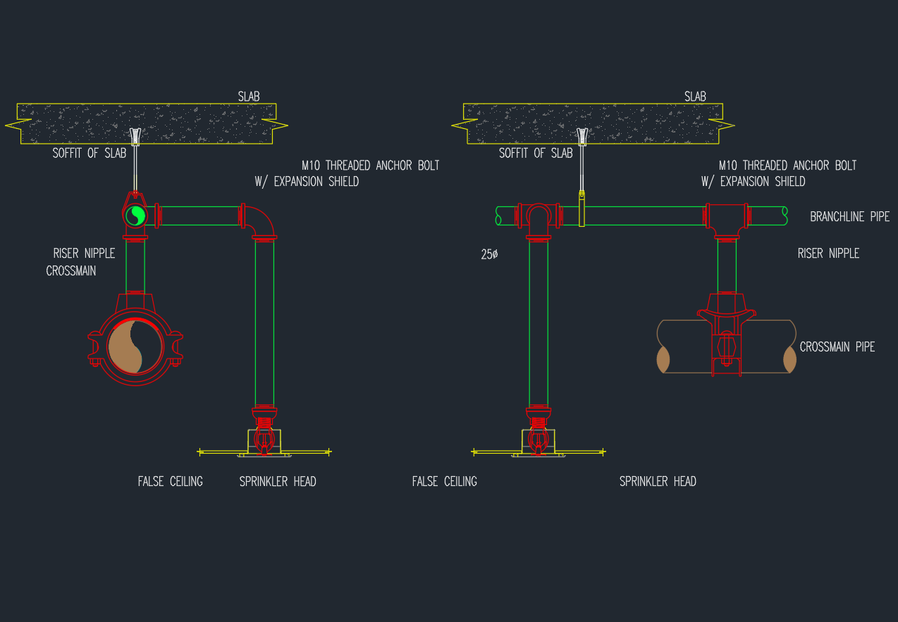
This pendent sprinkler head CAD block provides a reusable drawing element for fire protection plans, reflected ceiling plans, equipment details, and coordinated building documentation. It can help drafters maintain a consistent graphic appearance when showing sprinkler locations or preparing related legends and annotations.
A CAD block represents drawing geometry, not a complete fire protection design decision. Before using the file in construction documents, review its units, scale, insertion point, layer properties, linework, and plotted appearance. Sprinkler selection, spacing, orientation, and coordination must be verified against the project design criteria, product information, and requirements of the authority having jurisdiction.
Enhance your fire protection system designs with this detailed Sprinkler Head (pendent) DWG file, available as a high-quality CAD Block. Ideal for architects, engineers, and designers, this CAD Block accurately represents a pendent sprinkler head commonly used in residential, commercial, and industrial fire safety layouts. The DWG file is fully compatible with AutoCAD and other leading CAD software, ensuring seamless integration into your projects. Download this sprinkler head CAD Block to improve the accuracy and professionalism of your fire protection system drawings. Perfect for creating precise, code-compliant plans.
Please log in or register to download this file.
How a Pendent Sprinkler Is Represented in Drawings
A pendent sprinkler is generally shown extending downward from its connected piping, with its deflector positioned below the sprinkler body. The graphic representation may vary between a plan symbol, an elevation detail, and a more descriptive component drawing. Always confirm what view the downloaded geometry represents before placing it in a project file.
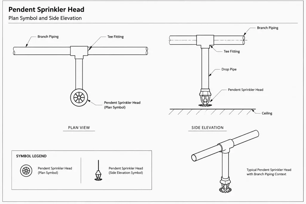
On a fire protection plan, a simplified symbol usually communicates location and type without reproducing every physical feature. A detail or elevation may use more recognizable geometry to explain orientation, ceiling relationships, or piping coordination. The project legend should define the intended meaning rather than relying on appearance alone.
Recommended CAD Review Workflow
- Inspect the file: Open the DWG in a controlled working file and check for unexpected layers, nested blocks, text, hatches, or reference content.
- Confirm drawing units: Compare the block with known project geometry before scaling or inserting it into a production drawing.
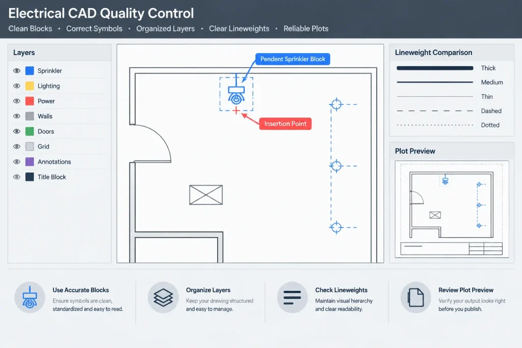
- Review the base point: Make sure the insertion point supports accurate placement at the intended sprinkler center or connection location.
- Apply project layers: Move or remap the geometry to the office layer system so color, lineweight, visibility, and plotting remain consistent.
- Check rotation and orientation: Verify that the block reads correctly in plan, elevation, section, or detail views.
- Test the plot: Review the symbol at the drawing’s intended output scale to confirm that its linework remains legible.
Drawing Coordination Considerations
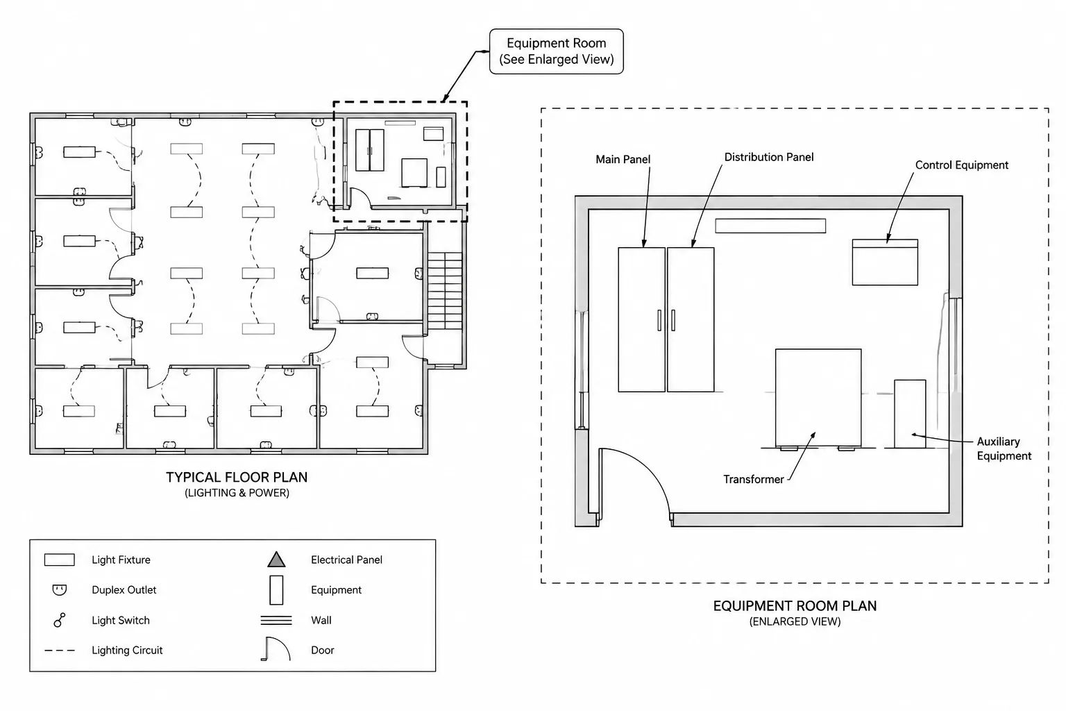
Sprinkler graphics are commonly coordinated with ceilings, lighting fixtures, air devices, structural elements, partitions, and other overhead systems. CAD placement should clearly communicate design intent while avoiding visual conflicts with nearby symbols and annotations. Crowded areas may require enlarged details, keyed notes, or separate coordination views.
Keep the sprinkler block distinct from piping lines, fittings, and generic ceiling markers. Consistent layers and a clear legend make it easier for reviewers to distinguish fire protection content from architectural, mechanical, and electrical backgrounds.

Useful Related Drawing References
- Fire protection legends: Define the meaning of sprinkler symbols, line types, abbreviations, and notes.
- Reflected ceiling plans: Show coordination between sprinkler locations and other ceiling-mounted elements.
- Piping layout drawings: Connect sprinkler symbols to branch piping and related system documentation.
- CAD layer standards: Control visibility, plotting, discipline ownership, and background coordination.
- Equipment details and sections: Clarify orientation where a plan symbol alone does not communicate the required relationship.
Verification Before Project Use
This block should be treated as editable drafting content rather than a verified manufacturer component or an approval symbol. Compare the geometry and annotation with the selected product documentation and the project’s fire protection design. Final drawings should be reviewed by the responsible qualified professional and coordinated with applicable requirements.
Frequently Asked Questions
What does pendent mean on a sprinkler drawing?
Pendent describes a sprinkler orientation in which the sprinkler extends downward from the connected piping. The exact plan or detail symbol may differ among offices, projects, and drawing legends.
Can this block be used in a reflected ceiling plan?
It may be incorporated into a reflected ceiling plan after its view, scale, insertion point, and graphic style have been checked. Use the project legend to identify the symbol clearly and coordinate it with other ceiling elements.
Does a CAD block confirm sprinkler spacing or code compliance?
No. A block supplies drawing geometry only. It does not establish acceptable spacing, coverage, product selection, hydraulic performance, or regulatory compliance. Those matters require project-specific design and professional verification.
Should the downloaded geometry remain on its original layers?
Not necessarily. Review the source layers and remap the block to the project’s approved layer structure when appropriate. Preserve any information needed to understand the geometry while removing unrelated content from the working file.
What should be checked if the block appears at the wrong size?
Check the source and destination drawing units before applying a scale adjustment. Also determine whether the geometry is a full-size component representation or a schematic symbol intended to remain readable at a plotted scale.










Leave a Reply
You must be logged in to post a comment.