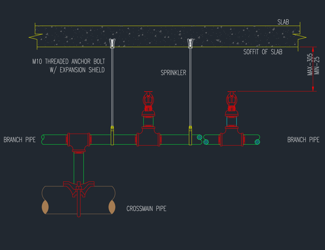
An upright sprinkler head CAD block provides a reusable graphic for identifying sprinkler components in fire protection drawings. Depending on the source view and office conventions, the block may support plan layouts, piping diagrams, equipment details, legends, or coordinated building-service documentation.
The drawing should be treated as a drafting resource rather than a complete fire protection design. Before using it in construction documents, review its view orientation, insertion point, layer assignment, linework, and annotation against the project CAD standard and approved fire protection criteria.
Download the Sprinkler Head (upright) DWG file, a high-quality CAD block designed for fire protection system layouts. This detailed AutoCAD drawing provides an accurate representation of an upright sprinkler head, making it ideal for architects, engineers, and designers working on building safety plans. The DWG file is fully compatible with AutoCAD and other popular CAD software, ensuring seamless integration into your fire sprinkler system designs. Perfect for MEP and architectural projects, this CAD block streamlines your workflow and enhances project accuracy. Suitable for commercial, industrial, and residential applications.
Please log in or register to download this file.
Understanding the Upright Sprinkler Graphic
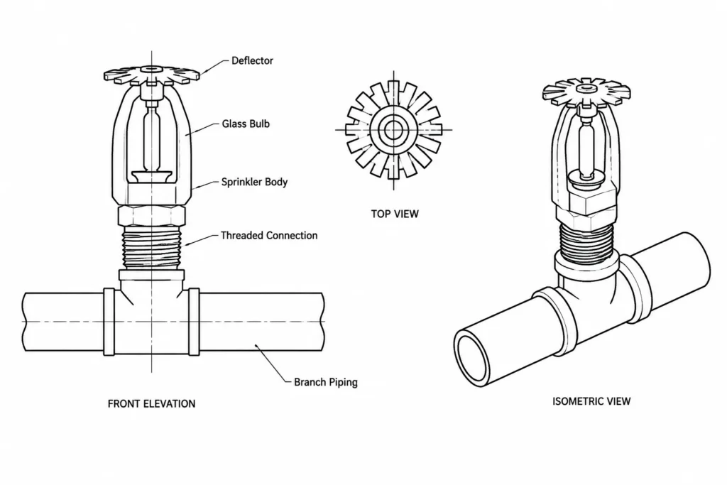
The term upright describes the installed orientation of the sprinkler assembly. In drawings, that orientation may be communicated through an elevation-style profile, a plan symbol, a diagrammatic representation, or a combination of graphics and labels. A detailed component block and a simplified plan symbol serve different documentation purposes, so users should confirm what the downloaded drawing represents before placement.
Where the CAD Block Fits in a Drawing Set
- Fire protection plans: Used as a component graphic or supporting symbol where the drawing convention calls for it.
- Piping diagrams: Helps identify the sprinkler type in relation to branch piping and other system components.
- Legends and schedules: Can provide a visual reference when paired with project-approved terminology.
- Coordination drawings: Supports comparison with architectural, structural, ceiling, and building-service information.
- Detail sheets: May be incorporated into a larger annotated detail after its geometry and purpose are verified.
CAD Review Checklist
Imported blocks often reflect the layer names, units, colors, linetypes, and object organization of the source file. Review these properties before adding the block to a production drawing.
- Confirm whether the geometry is intended for plan, elevation, detail, or diagram use.
- Check the drawing units and intended plotted appearance without assuming the block is already at project scale.
- Inspect the insertion point and rotation behavior for consistent placement.
- Move objects to approved fire protection layers while preserving meaningful linework.
- Remove duplicate geometry or unrelated objects only after confirming they are not required.
- Use clear naming so the block can be distinguished from other sprinkler symbols.
- Check that labels and leaders remain legible at the sheet’s intended output scale.
Coordination and Design Verification
A CAD symbol does not establish sprinkler selection, spacing, coverage, obstruction requirements, piping design, or installation approval. Those decisions depend on the approved system design, applicable requirements, product documentation, and review by qualified fire protection professionals.
When coordinating drawings, compare the sprinkler layout with ceilings, structural elements, lighting, diffusers, cable pathways, equipment, and other visible or concealed building features. Maintain consistent graphic conventions between the fire protection plan, reflected ceiling plan, single-line or riser documentation, legends, and related detail sheets.

Related Drawing Topics
This block is most useful when reviewed alongside references for fire sprinkler symbols, fire protection piping diagrams, MEP coordination drawings, CAD layer organization, and drawing legends and annotations. These topics help clarify how an individual component graphic fits into a complete and readable document set.
Frequently Asked Questions
What does an upright sprinkler head block represent?
It represents a sprinkler identified by its upright installation orientation. The exact graphic may be a profile, plan symbol, or diagrammatic component, so its view should be checked before use.
Can the block be used directly in a fire protection plan?
It can be incorporated into a drawing after its units, scale behavior, layers, view, and graphic convention are verified. Project documentation should also distinguish between a detailed component block and the simplified symbol used for repeated plan locations.

Does the DWG determine sprinkler spacing or coverage?
No. The block is drawing geometry and does not determine design criteria, product performance, spacing, coverage, or installation compliance. Those items require project-specific engineering and approved product information.
What should be checked after importing the file?
Review units, insertion point, layer assignments, linetypes, colors, object extents, annotations, and plotted clarity. Also check for duplicate or unrelated geometry before saving the block into a project library.
How should the block be named in a CAD library?
Use a clear naming convention that identifies the component as an upright sprinkler and, where relevant, distinguishes its drawing view. Avoid adding performance or product claims that are not supported by verified project information.












Leave a Reply
You must be logged in to post a comment.