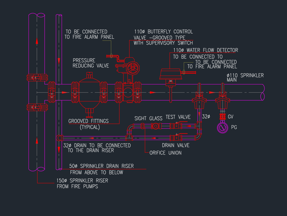
A typical sprinkler zone control station detail AutoCAD drawing provides a reusable drafting reference for documenting the arrangement, identification, and connections associated with a sprinkler zone. It can support detail sheets, fire protection plans, riser documentation, and multidisciplinary coordination.
Because requirements and drawing conventions vary by project, the detail should be treated as an editable reference rather than a complete project specification. Review every symbol, note, connection, and component against the approved fire protection design and applicable project criteria before issuing construction documents.
Discover a high-quality DWG file for a **Typical Sprinkler Zone Control Station Detail**, perfect for architects, engineers, and designers working on fire protection systems. This comprehensive CAD block clearly illustrates the essential components required for a sprinkler zone control station, ensuring compliance with industry standards. Suitable for use in commercial and residential building plans, this DWG file streamlines your project workflow. Fully compatible with AutoCAD and other leading CAD software, this file allows easy integration into your construction documents, saving you valuable drafting time while enhancing design accuracy.
Please log in or register to download this file.
How to Read the Zone Control Station Detail
Begin by following the indicated flow path and identifying how the assembly connects to the sprinkler piping. Zone control station details commonly communicate functional items such as an indicating control valve, flow detection, pressure indication, and test or drain provisions. Confirm which of these items are actually shown in the downloaded drawing rather than assuming that every typical component is included.

Review leaders, abbreviations, line types, and equipment tags together. A symbol may represent a physical device, while nearby notes define its function, monitoring requirement, installation relationship, or connection to another drawing.
CAD Review and Editing Checklist
- Layer organization: Move geometry, text, dimensions, and annotation to the project’s approved CAD layers as needed.
- Symbol consistency: Compare valve, detector, gauge, piping, and drain symbols with the project legend.
- Text standards: Match the office text style, plotted height, abbreviations, and capitalization conventions.
- Drawing scale: Verify that notes, leaders, and symbols remain readable at the intended sheet scale.
- References: Check detail callouts, riser references, equipment tags, and sheet references for consistency.
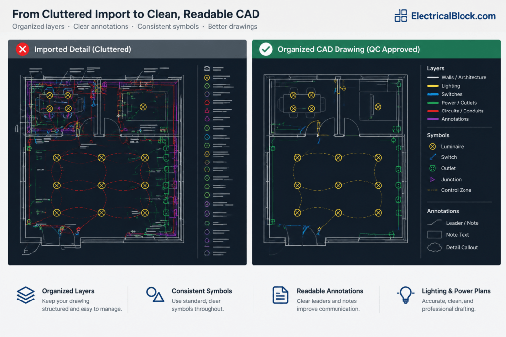
- File cleanup: Inspect unused layers, duplicate geometry, disconnected leaders, and unnecessary embedded content before insertion.
Coordination With Other Drawings
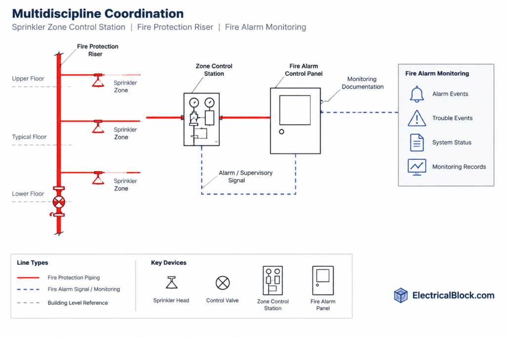
A zone control station can affect several documentation disciplines. Coordinate its location and piping relationships with the fire protection plan and riser diagram. Where monitoring devices are represented, coordinate device identification and interface notes with the fire alarm drawings. Architectural access, equipment clearances, and room identification should also agree with the corresponding plan set.
Related drafting references may include sprinkler legends, valve symbols, fire alarm interface diagrams, equipment-room layouts, riser diagrams, and CAD layer guidance. Reviewing these related drawing types helps prevent inconsistent tags or duplicated notes across the construction documents.
Project Verification
The word typical does not mean universally applicable. Confirm the assembly configuration, monitoring intent, accessibility, drainage routing, and annotation with the responsible design professional and current project requirements. Do not rely on a generic CAD detail as evidence of code compliance or final design approval.
Frequently Asked Questions
What is a sprinkler zone control station detail?
It is a drafting detail used to show the arrangement and identification of components that control, monitor, or support a defined sprinkler piping zone.
Can this detail be inserted directly into a project sheet?
It can be used as a starting point, but its layers, text, symbols, references, and component arrangement should be checked against the project CAD standards and approved fire protection design.
How does this detail relate to fire alarm drawings?
Where flow or valve-status monitoring is required, the fire protection detail and fire alarm documentation should use coordinated device tags, interface descriptions, and drawing references.
What should be checked after importing the DWG?
Check units, insertion scale, layers, fonts, line types, symbol definitions, leader connections, plotting appearance, and referenced notes. Also confirm that no project-specific information was unintentionally carried into the file.
Does a typical CAD detail establish code compliance?
No. Compliance depends on the complete project design, adopted requirements, equipment selection, installation conditions, and professional review.












Leave a Reply
You must be logged in to post a comment.