
A fire fighting riser diagram is a schematic drawing used to communicate how fire protection equipment and distribution piping relate across a building. Unlike a floor plan, it emphasizes system connections, vertical relationships, equipment sequence, and labeled branches rather than exact physical routing.
The downloadable DWG below can support CAD drafting and drawing coordination. Before incorporating it into project documents, review its symbols, notes, layers, equipment tags, and connection logic against the project design criteria and applicable authority requirements.
Download a comprehensive Fire Fighting Riser Diagram DWG file, designed as a precise CAD Block for your fire protection projects. This detailed diagram illustrates the essential components and layout of a fire fighting riser system, ensuring clarity and compliance for engineers, architects, and designers. Perfect for use in commercial and residential building plans, the file is fully compatible with AutoCAD and similar CAD software, allowing seamless integration into your design workflow. Enhance your fire safety designs with this ready-to-use, editable Fire Fighting Riser Diagram, ideal for construction documentation and MEP coordination.
Please log in or register to download this file.
How to Read a Fire Fighting Riser Diagram
Begin by identifying the system supply and tracing the indicated flow path through the diagram. Follow connected lines toward risers, branches, zones, and terminal system references. Arrows, line types, equipment tags, and nearby notes help explain the intended relationship between components.
A riser diagram is generally schematic. Components may be arranged for clarity rather than shown in their actual installed positions. Use floor plans, equipment layouts, sections, schedules, and details when evaluating physical location, access, routing, and coordination.
Equipment and Information to Look For
The exact content of a fire protection drawing depends on the project and the source file. When reviewing this DWG, check whether the diagram identifies the following categories:
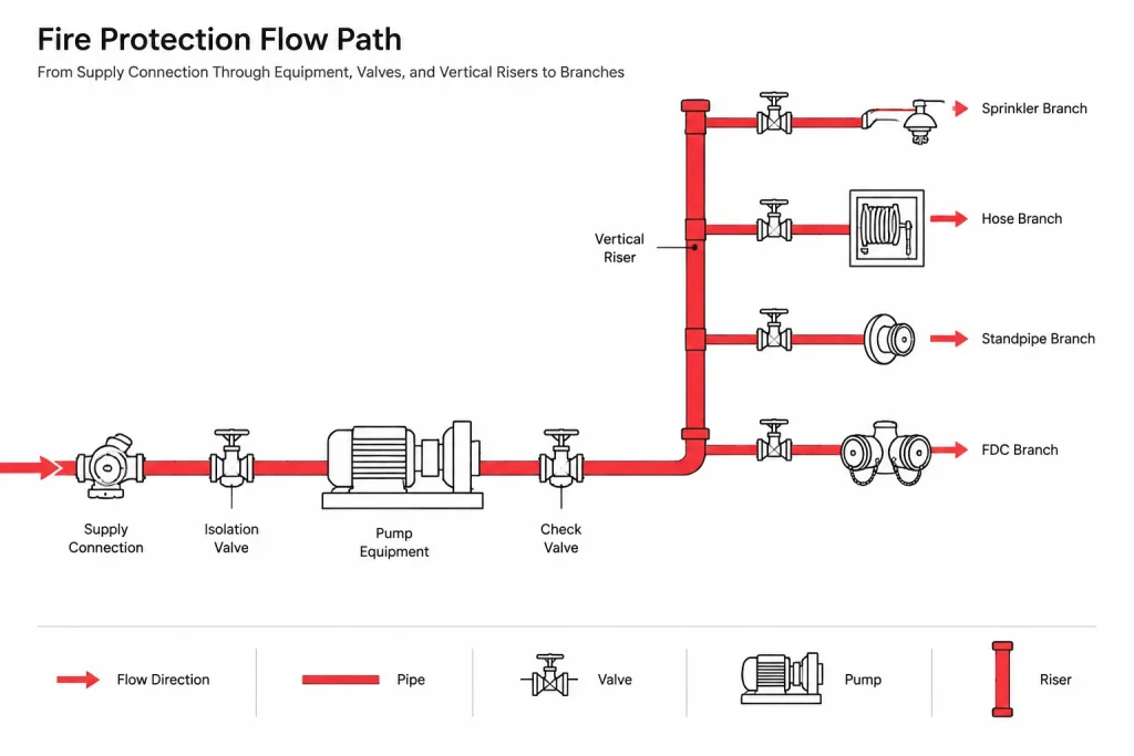
- Water supply: The point where the depicted system begins and any referenced source or storage equipment.
- Pressure-related equipment: Pumps, associated controls, and connected piping when included in the design.
- Valves and control points: Isolation, control, check, test, or drain components represented by symbols and tags.
- Vertical distribution: Risers and their relationships to floors, zones, or connected fire protection systems.
- Monitoring interfaces: Flow, pressure, supervisory, or alarm-related devices when shown.
- Drawing references: Notes, detail callouts, equipment identifiers, and references to related plans or schedules.
This list is a review framework and does not confirm that every category appears in the downloadable file. The drawing itself should remain the source of truth for its included content.
CAD Review and Documentation Workflow
Inspect the file before editing
Open the DWG in a controlled working copy and check for missing fonts, external references, custom line types, proxy objects, and block dependencies. Confirm that annotation remains readable and that the drawing units and insertion behavior align with the destination project.
Review layers and graphic hierarchy
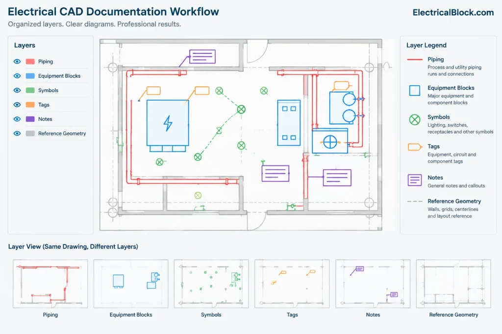
Map imported layers to the project CAD standard rather than placing the entire diagram on a single general layer. Separate piping, equipment, symbols, annotations, reference geometry, and revision information where the source organization allows it. A clear lineweight and line-type hierarchy makes the schematic easier to follow.
Preserve symbol meaning
Do not assume that a familiar-looking symbol has the same meaning in every office or project. Compare blocks and abbreviations with the drawing legend. If a symbol is changed, update its legend entry, equipment tag, and related references so the document remains internally consistent.

Coordinate related drawings
Compare the riser with fire protection plans, equipment layouts, architectural floor references, structural constraints, and relevant MEP drawings. System names, zone labels, equipment identifiers, and connection points should agree throughout the document set.
Useful Related Drawing Topics
This file is best understood alongside reference content about electrical and MEP CAD blocks, equipment layouts, drawing legends, annotation practices, CAD layers, and single-line diagram concepts. Although a fire protection riser and an electrical single-line diagram represent different systems, both use simplified connections and symbols to communicate system relationships without depicting every physical routing detail.
Important Design Limitation
An editable CAD detail is a drafting resource, not automatic confirmation of project suitability or code compliance. Fire protection design depends on building conditions, system criteria, adopted requirements, equipment documentation, and review by qualified professionals and relevant authorities. Verify the completed drawing before it is issued for permitting, coordination, fabrication, or construction.
Frequently Asked Questions
What does a fire fighting riser diagram show?
It shows schematic relationships among the supply, equipment, vertical risers, branches, zones, valves, and monitoring components included by the designer. Its purpose is system communication rather than exact spatial placement.
Is a riser diagram the same as a fire protection floor plan?
No. A floor plan emphasizes horizontal location and routing within a building area. A riser diagram emphasizes system sequence, vertical distribution, and connections between building levels or zones.
Can the DWG be inserted directly into another project?
The source describes the file as editable and compatible with AutoCAD and similar CAD software. Even so, users should inspect units, layers, blocks, fonts, line types, notes, and external references before integrating it into another drawing set.
How should unfamiliar equipment symbols be interpreted?
Check the drawing legend, abbreviations, equipment tags, and referenced details. Avoid identifying a symbol solely by appearance because CAD symbol conventions can vary among organizations and projects.
Does the diagram establish actual pipe routing?
Not necessarily. Riser diagrams are commonly arranged for schematic clarity. Actual routing and equipment locations should be coordinated with plans, sections, layouts, and field conditions.
Is the downloaded drawing sufficient for approval or construction?
No standalone CAD file should be treated as automatic approval or as a complete project design. It must be reviewed and adapted by qualified project professionals in accordance with applicable requirements and coordinated documents.












Leave a Reply
You must be logged in to post a comment.