
An alarm check valve detail DWG is a drafting reference used to represent valve equipment associated with a wet-pipe sprinkler system. Depending on the drawing set, the detail may support a sprinkler riser diagram, equipment layout, enlarged assembly view, or coordinated fire protection plan.
Before placing the block into project documents, review its geometry, labels, insertion point, units, and layer organization. The downloaded detail should be treated as a CAD resource rather than a complete installation design. Final equipment selection, arrangement, and documentation must be coordinated with the project requirements and reviewed by a qualified fire protection professional.
Explore our high-quality Alarm Check Valve Detail DWG file, designed for professionals seeking precise CAD blocks for fire protection systems. This detailed drawing provides a comprehensive representation of an alarm check valve, essential for wet pipe sprinkler systems in commercial and industrial buildings. The DWG file is fully compatible with AutoCAD and other leading CAD software, ensuring seamless integration into your design projects. Perfect for architects, engineers, and contractors, this CAD block simplifies system layout and enhances project accuracy. Download the Alarm Check Valve Detail for efficient and reliable fire safety designs.
Please log in or register to download this file.
How an Alarm Check Valve Is Represented in Fire Protection Drawings
An alarm check valve is associated with waterflow monitoring and alarm functions in a wet-pipe sprinkler arrangement. In CAD documentation, it may be shown as part of a larger riser assembly or as a separate detail that clarifies equipment relationships. The exact components and annotations vary by system design, manufacturer, and project documentation standard.
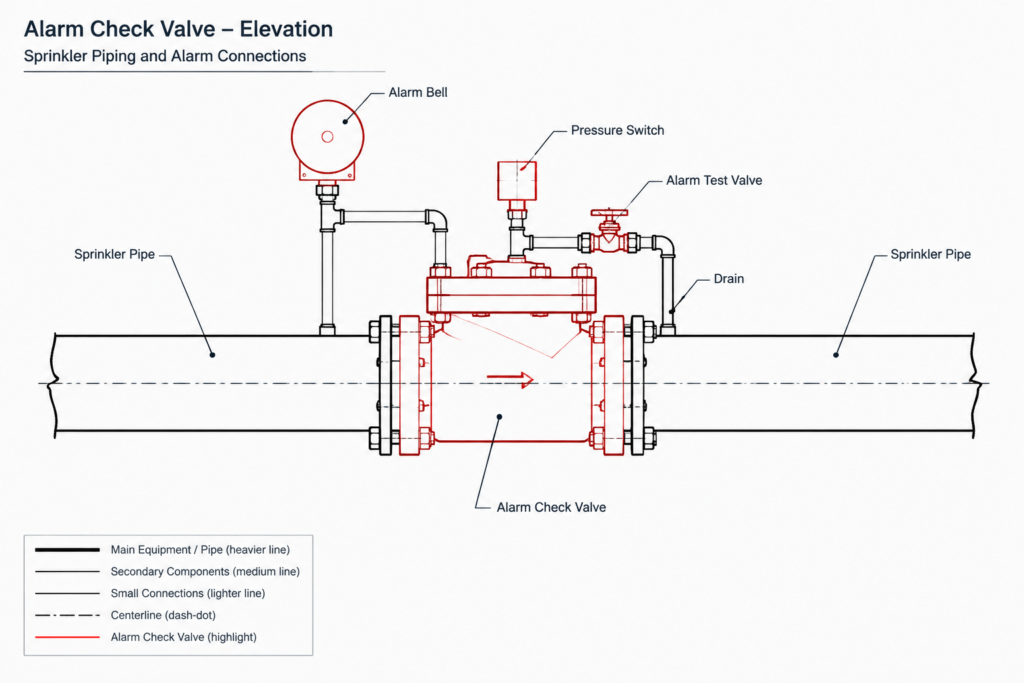
This type of detail should not be confused with a simplified plan symbol. A plan symbol identifies general equipment location, while an enlarged detail can communicate assembly relationships, connection intent, labels, and coordination information. A single-line or riser diagram provides broader system context and shows how the valve relates to water supply, sprinkler piping, alarm interfaces, and other system elements.
Recommended CAD Review Workflow
Inspect the source drawing
- Confirm that the drawing opens correctly and that the visible geometry is complete.
- Check the drawing units and scale conventions before inserting or referencing the file.
- Look for duplicate objects, disconnected linework, unexpected proxy objects, or unnecessary background geometry.
- Review text styles, dimension styles, linetypes, and annotation behavior.
Organize the detail for project use
- Place equipment outlines, piping, centerlines, text, and reference information on appropriate project layers.
- Use a clear block name that distinguishes the alarm check valve detail from general valve symbols.
- Preserve legibility when the detail is viewed at the intended plotted scale.
- Avoid exploding the block unless editing is necessary and consistent with the office CAD workflow.
Coordinate related documentation
- Compare the detail with the sprinkler riser diagram and fire protection plan.
- Coordinate alarm-related references with the applicable fire alarm drawings and interface notes.
- Use consistent equipment terminology across plans, schedules, legends, and detail callouts.
- Verify that the detail does not conflict with architectural, structural, or other building-service drawings.
Drawing Elements to Verify
The presence and arrangement of individual components must be confirmed from the actual DWG and the selected equipment documentation. When reviewing an alarm check valve assembly detail, drafters commonly check the following categories:
- Main flow path: Piping direction and the relationship between supply-side and system-side connections.
- Valve identification: Clear labeling that separates the alarm check valve from nearby control, drain, test, or monitoring components.
- Alarm interface: Graphic or note-based references showing how waterflow alarm functions coordinate with other documentation.
- Service access: Drawing clarity around equipment that may require inspection, testing, or maintenance.
- Callouts and notes: Consistent leaders, abbreviations, equipment tags, and cross-references.
- System context: A clear relationship to the sprinkler riser, connected piping, and relevant drawing references.
Using the Detail Without Overstating Design Intent
A downloaded CAD block can reduce repetitive drafting, but it does not establish that a particular assembly is approved or suitable for a project. Do not rely on generic geometry as a substitute for coordinated design information. Verify the detail against the project specifications, approved equipment data, authority requirements, and the responsible design professional’s direction.
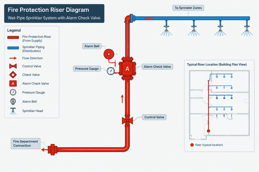
For a more complete drawing package, coordinate this detail with related content such as sprinkler riser diagram concepts, valve symbols, fire alarm interface diagrams, equipment legends, piping annotations, and CAD layer management. These references help readers understand where an enlarged valve detail fits within the overall documentation set.
Frequently Asked Questions
What is an alarm check valve detail DWG used for?
It is used as a CAD drafting reference for documenting an alarm check valve or related wet-pipe sprinkler assembly. It may appear in an enlarged detail, riser diagram, equipment layout, or coordinated fire protection drawing set.
Is a valve detail the same as a valve symbol?
No. A symbol is typically a simplified graphic used on plans or diagrams. A detail provides more visual information about equipment relationships, connections, labels, or assembly context.

What should be checked before inserting the DWG?
Check units, scale conventions, layers, text styles, linetypes, insertion behavior, and visible geometry. Also confirm that its terminology and graphic conventions match the destination drawing set.
Can this CAD detail determine the final system arrangement?
No. The block is a drafting resource. The final arrangement must reflect project-specific design documents, selected equipment information, coordination requirements, and professional review.
Which drawings should be coordinated with this detail?
Typical coordination references include the sprinkler plan, riser diagram, equipment legend, fire alarm interface documentation, architectural background, and other building-service drawings that affect equipment location or access.












Leave a Reply
You must be logged in to post a comment.