
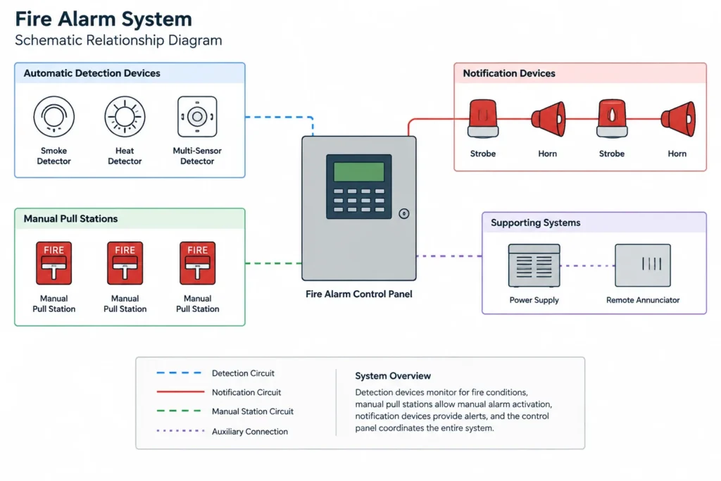
A fire alarm system diagram helps design teams communicate how detection, control, and notification elements relate within a building drawing set. This page provides a DWG resource described as including smoke detectors, alarm control panels, and emergency notification devices for use in CAD-based documentation.
Before incorporating the drawing into another file, review its symbols, annotations, linework, and organization against the receiving project’s drafting conventions. Fire alarm graphics can vary among consultants, jurisdictions, and drawing templates, so each symbol should be interpreted through the applicable legend rather than by appearance alone.
Discover a highly detailed fire alarm system diagram available as a DWG file, perfect for engineers and architects. This CAD Block provides a comprehensive layout of a fire alarm system, including smoke detectors, alarm control panels, and emergency notification devices. Ideal for use in commercial and residential building projects, this fire alarm system diagram streamlines design and planning processes. The DWG file format ensures full compatibility with AutoCAD and other major CAD software, enabling easy customization and integration into your construction drawings. Download this essential resource to enhance your fire safety designs.
Please log in or register to download this file.
How to Read the Fire Alarm CAD Drawing
Begin by identifying the main control equipment and then trace the linework associated with detection and notification devices. Depending on the drawing method, connecting lines may communicate system relationships, circuit grouping, or routing intent. Do not assume that a line represents a physical cable path unless the notes and legend clearly define it that way.

Device graphics should remain visually distinct from architectural backgrounds, lighting symbols, power symbols, and other low-voltage systems. Clear separation is especially important on coordinated plans where several disciplines share the same floor plan.
Drawing Elements to Review
- Control equipment: Confirm that panel symbols and labels can be distinguished from field devices.
- Detection devices: Check how smoke detectors and any other initiating devices are represented in the legend.
- Notification devices: Review symbol types, labels, and their relationship to the surrounding plan.
- System linework: Determine whether lines indicate logical connections, circuit relationships, or proposed routing.
- Annotations: Look for tags, abbreviations, notes, and references that explain device identity or drawing intent.
- Background coordination: Verify that walls, rooms, doors, ceilings, and equipment backgrounds remain readable without competing with system graphics.
CAD Coordination and Layer Workflow
After opening the DWG, inspect the layer names, object properties, text styles, blocks, and external references before copying content into a project file. Keeping fire alarm devices, connecting linework, annotations, and architectural backgrounds logically separated makes later revisions easier and reduces accidental edits.
When symbols are moved into another drawing, confirm that their scale, orientation, attributes, and lineweight behavior still match the destination file. A block that looks correct in model space may display differently in a plotted sheet because of layer overrides, annotation settings, or plotting conventions.
Related Drawing Context
A fire alarm diagram is often reviewed alongside electrical legends, floor plans, reflected ceiling plans, equipment layouts, riser or single-line diagrams, and cable or conduit documentation. These related drawings answer different questions: a plan communicates location, while a system-oriented diagram emphasizes functional relationships and organization.
Important Documentation Check
This CAD resource should be treated as a drafting reference rather than automatic approval for construction. Device selection, placement, circuit design, accessibility, coordination, and compliance must be verified for the actual project by qualified professionals using the applicable requirements and approved design documents.
Fire Alarm System Diagram FAQ
What does this fire alarm system diagram include?
The source description identifies smoke detectors, alarm control panels, and emergency notification devices. Open the DWG and review its legend and annotations to confirm the specific graphics provided.
Can the DWG be added directly to a project drawing?
It can be used as a CAD reference, but its layers, blocks, text, units, scale behavior, and symbol conventions should be checked before integration. Project-specific design information still requires professional verification.

Is a fire alarm plan the same as a system diagram?
Not necessarily. A plan commonly emphasizes device locations within building geometry, while a system diagram may emphasize functional connections and equipment relationships. Some drawing files combine aspects of both.
Why is the symbol legend important?
Fire alarm symbols are not interpreted reliably by shape alone. The legend establishes what each graphic, abbreviation, tag, and line type means within that particular drawing set.
What should be checked after importing the CAD content?
Review layer assignment, block integrity, text readability, lineweights, symbol scale, plotting appearance, and coordination with architectural and electrical backgrounds.












Leave a Reply
You must be logged in to post a comment.