
A single line diagram presents an electrical power system in a simplified form so readers can understand how major equipment and circuit paths relate to one another. Rather than showing every conductor separately, the drawing uses standardized-looking symbols, labels, and connecting lines to communicate the system arrangement clearly.
This DWG and CAD block resource is intended as a reference for reviewing power distribution concepts, preparing documentation, and studying how a single-line view organizes equipment relationships. Use it as a drafting aid and educational reference, not as a substitute for project-specific engineering review.
Discover a detailed Single Line Diagram of Power System available as a DWG file and CAD Block, perfect for electrical engineers and designers. This professional drawing illustrates the core components and connections within a power system, streamlining your project planning and documentation. Ideal for substation layouts, power distribution, and educational purposes, the file is fully compatible with AutoCAD and similar CAD software. Easily editable, the single line diagram enhances workflow efficiency and ensures accurate representation of electrical circuits. Download now to elevate your power system design projects with this essential CAD resource.

Please log in or register to download this file.
How to read a power system single line diagram
Begin by identifying the direction of power flow and then follow the connected equipment through the diagram. Depending on the drawing, the arrangement may show sources, transformers, switchgear, distribution equipment, feeders, and loads as related functional elements. The single-line format emphasizes connectivity and system organization rather than physical installation detail.
Symbols, labels, and the drawing legend
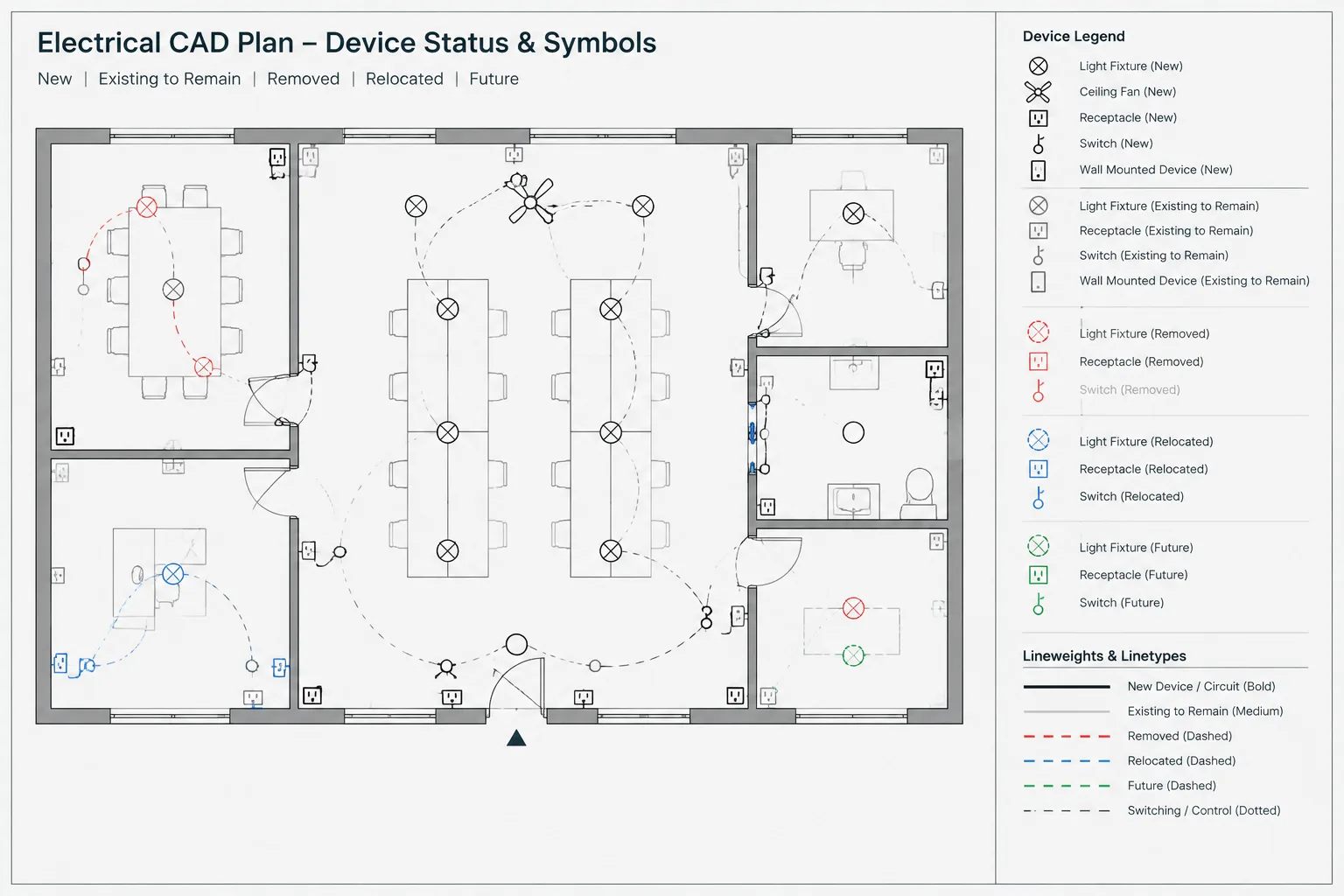
Symbols provide a compact visual language for electrical equipment and circuit functions. Labels add the information needed to distinguish equipment, sections, or destinations. A drawing legend is especially important because symbol conventions can vary between offices, projects, and CAD libraries. Always compare unfamiliar symbols with the legend or surrounding notes before interpreting them.
Using the DWG as a CAD reference
In a CAD workflow, review the drawing with attention to layers, block definitions, line types, text styles, and annotation organization. Separating equipment graphics, connecting lines, notes, and reference information helps make a drawing easier to edit and coordinate. Before reusing any block, check its orientation, insertion behavior, layer assignments, and compatibility with the destination drawing template.

Relationship to other electrical drawings
- Plan drawings: show the approximate physical placement of equipment, pathways, and outlets within a space or facility.
- Panel schedules: organize circuit and load information associated with distribution equipment.
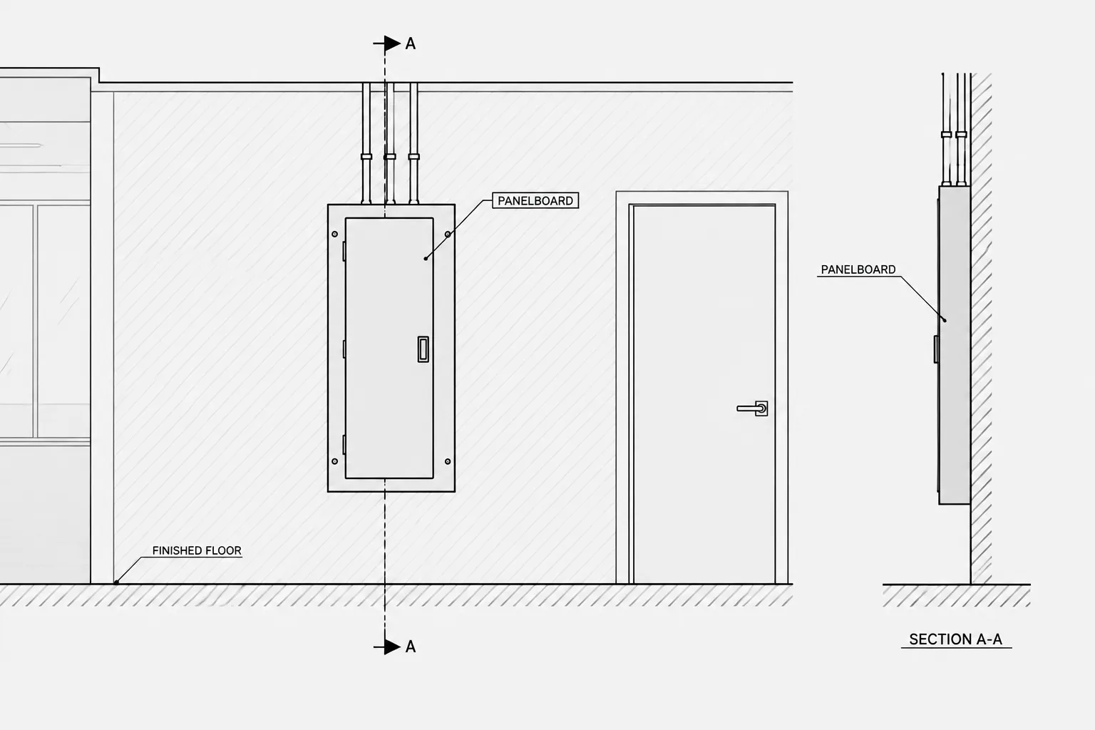
- Equipment layouts: provide a more physical view of cabinets, switchgear, transformers, or related assemblies.
- Single line diagrams: summarize functional relationships and power distribution paths in a compact format.
Reference-use guidance
Use the drawing to study drafting conventions, compare diagram organization, or develop a starting point for project documentation. A downloaded CAD resource should be reviewed against the project scope, design criteria, equipment information, and applicable engineering requirements before it is incorporated into a deliverable. Editing a block or diagram does not by itself verify the electrical design or the physical installation.
Frequently asked questions
What is a single line diagram?
A single line diagram is a simplified representation of an electrical power system. It uses one line to represent a circuit path while symbols and labels identify functional equipment and relationships.
What can this AutoCAD drawing be used for?
The DWG resource can serve as a visual reference for studying power distribution organization, reviewing CAD drafting methods, and developing documentation concepts. It should be checked and adapted for the specific project.

Why is a legend important?
A legend explains the symbol and notation conventions used in a drawing. It helps readers interpret equipment, connections, and annotations consistently, particularly when a diagram uses office-specific CAD blocks.
Does a single line diagram show the physical installation?
Not usually. It focuses on functional relationships and connectivity. Physical location, routing, clearances, mounting, and installation details are generally documented in other drawing types.
What should be checked before reusing a DWG block?
Review the block geometry, labels, layer assignments, linework, annotation behavior, and drawing orientation. Confirm that the content matches the project requirements and has received appropriate engineering review before publication or construction use.










Leave a Reply
You must be logged in to post a comment.