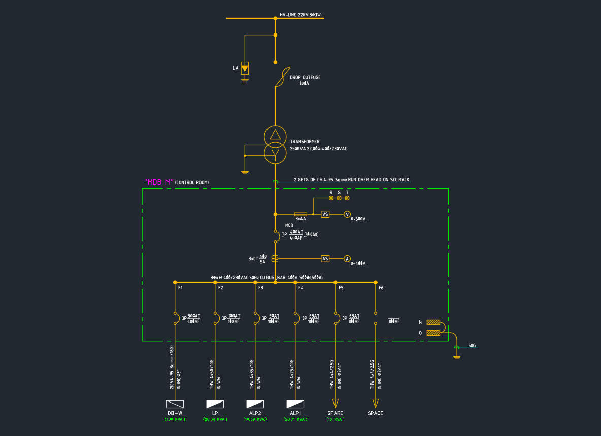
A single line diagram of an MDB summarizes how a Main Distribution Board connects an incoming electrical source with bus arrangements, protective devices, and outgoing feeders. Unlike a physical wiring layout, a single-line drawing uses simplified lines and symbols to communicate the distribution hierarchy clearly.
The DWG resource on this page can support drafting, coordination, and educational review. Before adapting it to project documents, compare its symbols, labels, circuit relationships, and drawing conventions with the requirements of the specific design.
Enhance your electrical design projects with our detailed Single Line Diagram of MDB (Main Distribution Board) available as a high-quality DWG file. This AutoCAD Electrical CAD drawing provides a clear and precise representation of MDB wiring and connections, making it ideal for electrical engineers and designers. The CAD block includes comprehensive circuit arrangements, symbols, and labeling for easy customization and implementation in various industrial and commercial power distribution systems. Fully compatible with AutoCAD and other popular CAD software, this file streamlines the design and documentation process, saving you time and ensuring accuracy in your electrical layouts. Download now to improve your project efficiency and professionalism.
Please log in or register to download this file.
How to Read an MDB Single Line Diagram
Begin at the incoming source and follow the main connection through the distribution board toward the outgoing circuits. This reading direction helps reveal the intended power flow and the relationship between the MDB and downstream equipment.

Protective and switching devices are represented with schematic symbols rather than physical equipment outlines. Lines show electrical relationships, while identifiers and annotations help connect diagram elements with schedules, equipment references, and other project drawings.
Key Drawing Elements to Review
- Incoming source: Confirm that the source description and connection point are clearly identified.
- Main distribution path: Trace the relationship between the incoming section, bus arrangement, and outgoing feeders.
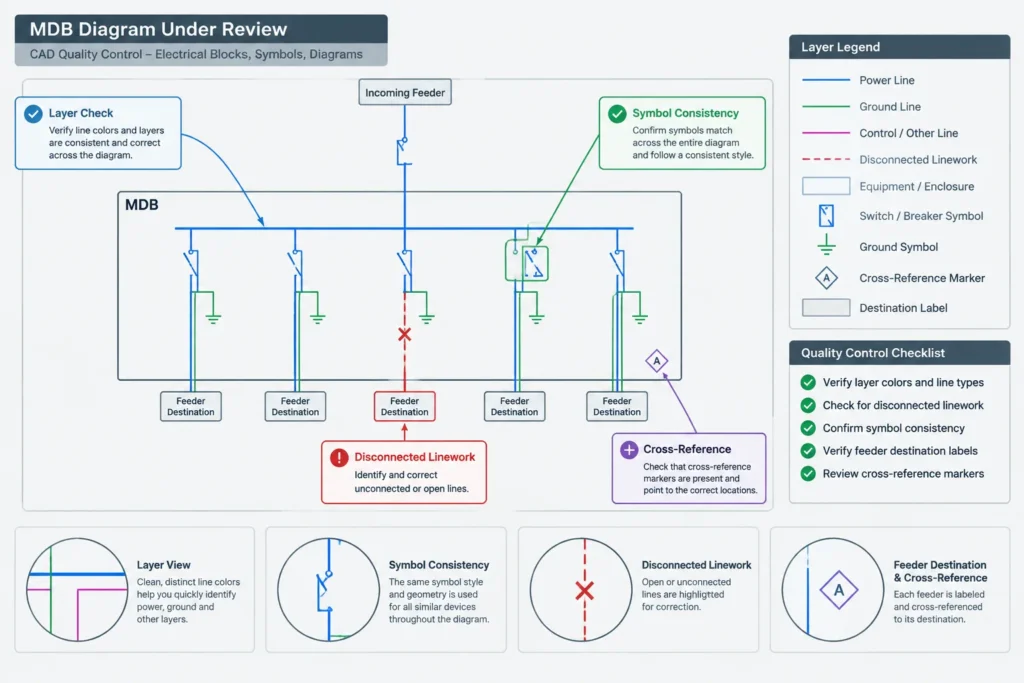
- Protective devices: Check that device symbols are consistent and that each device can be associated with the correct circuit.
- Feeder labels: Review circuit names, equipment references, and continuation notes for clarity.
- Symbol legend: Make sure the symbols used in the diagram match the project legend and drafting conventions.
- Cross-references: Coordinate references to panel schedules, equipment layouts, riser diagrams, and related sheets.
Practical AutoCAD Documentation Checks
When editing the DWG, keep electrical symbols, connecting linework, text, and reference information organized logically. Consistent layers and text styles make the diagram easier to revise, compare, and issue with a larger drawing set.
A useful quality-control review includes checking for disconnected linework, duplicated symbols, unclear feeder destinations, inconsistent identifiers, and annotations that overlap diagram elements. Also verify that referenced equipment names match the terminology used elsewhere in the project documentation.

Relationship to Other Electrical Drawings
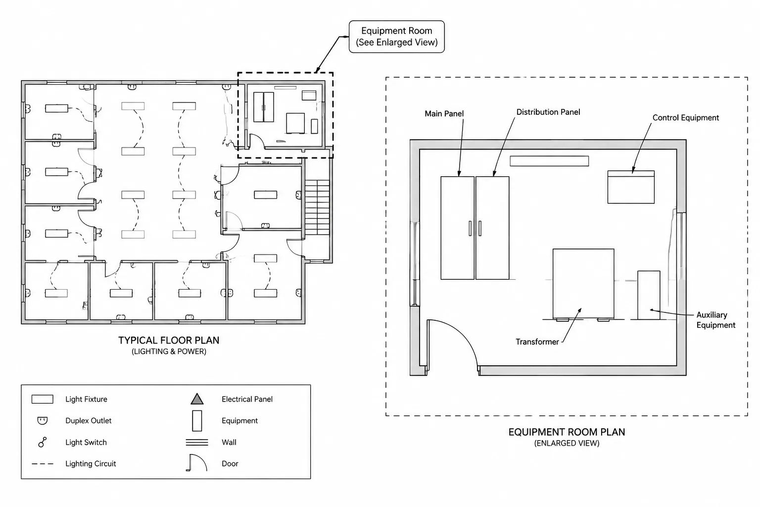
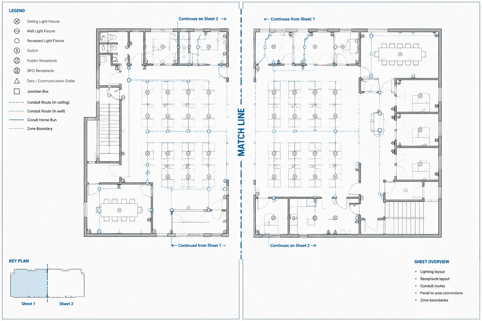
An MDB single line diagram explains distribution relationships, but it does not replace every supporting document. A panel schedule organizes circuit information, an equipment layout shows physical location, and cable or conduit drawings document routing. Legends and symbol references define the graphical language shared across these documents.
Use the drawing as a drafting resource rather than an automatically approved design. Final project documents should be reviewed for site conditions, equipment selections, applicable requirements, and coordination with the complete electrical design.
Frequently Asked Questions
What does MDB mean on an electrical drawing?
MDB commonly means Main Distribution Board. On a single-line diagram, it represents a central distribution point between an incoming source and outgoing feeders.
Is a single line diagram the same as a wiring diagram?
No. A single-line diagram simplifies electrical distribution into symbolic connections. A wiring diagram generally provides more detailed conductor, terminal, or control information.
Is an MDB diagram the same as a panel schedule?
No. The diagram shows electrical relationships and distribution flow, while a panel schedule organizes circuit and equipment information in a schedule format. The documents should use coordinated identifiers.
What should be checked before reusing the DWG?
Review the symbol conventions, labels, feeder destinations, protective-device representation, cross-references, layers, and drawing notes. Remove or revise information that does not apply to the intended project.
Can this drawing be used directly for construction?
A CAD drawing should not be treated as project-ready without verification. A qualified design professional should confirm the electrical arrangement, equipment information, applicable requirements, and coordination with the rest of the drawing set.










Leave a Reply
You must be logged in to post a comment.