
A pipe hanger detail AutoCAD drawing helps document how a piping support assembly is represented within construction or engineering drawings. Before incorporating the DWG into a project, review its geometry, drawing units, layers, annotations, and intended view so the detail aligns with the surrounding documentation.
This type of CAD resource can support plumbing, HVAC, and mechanical drawing coordination, but it should not be treated as a project-specific support design without verification. Pipe material, routing, loading, movement, attachment conditions, and the supporting structure can all affect the final engineered detail.
Discover a high-quality Pipe Hanger Detail DWG file, perfect for your construction and engineering projects. This CAD Block provides a precise and detailed illustration of pipe hanger assemblies, making it ideal for plumbing, HVAC, and mechanical system designs. The file is fully compatible with AutoCAD and other popular CAD software, ensuring easy integration into your existing drawings. Enhance your project accuracy and efficiency with this ready-to-use Pipe Hanger Detail, suitable for architects, engineers, and drafters seeking professional CAD resources for their technical documentation.
Please log in or register to download this file.
How to Review the Pipe Hanger Detail
Open the file in the intended CAD application and inspect the drawing before copying it into a working sheet. Confirm that the geometry imports correctly and determine whether the content is organized as a reusable block, separate objects, or a complete detail. Software compatibility can depend on the target application and its DWG support, so visual review is important.
CAD Documentation Checklist
- Drawing units: Identify the source units before scaling or inserting the detail.
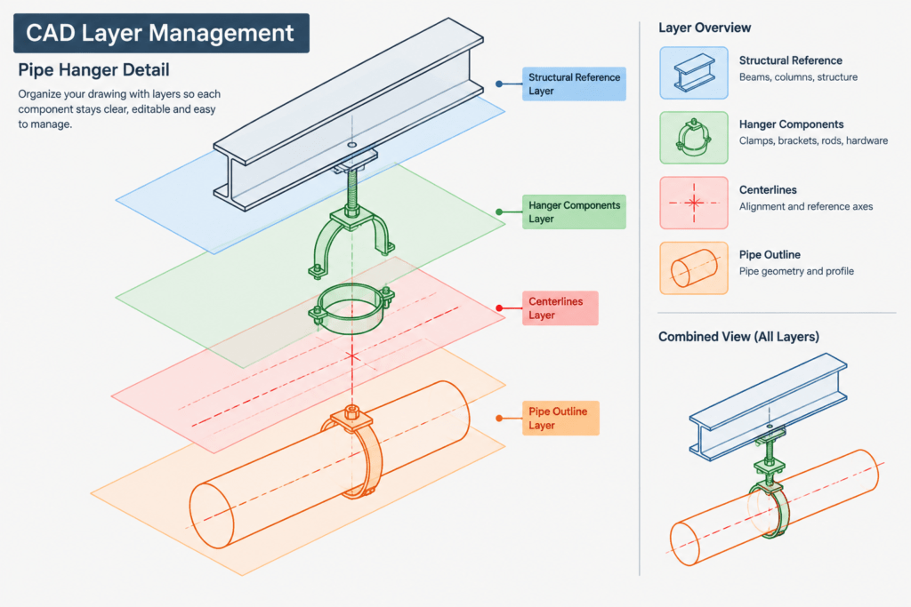
- Layers: Review layer names, colors, linetypes, and visibility against the project CAD standard.
- Linework: Check for duplicate entities, disconnected geometry, unnecessary fills, or elements placed far from the main detail.
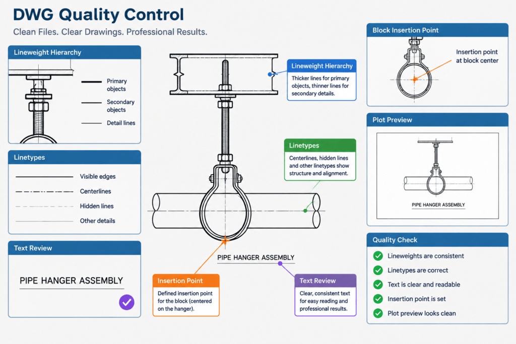
- Annotations: Verify that notes, leaders, symbols, and text styles remain readable and appropriate for the sheet.
- Reference geometry: Distinguish the hanger assembly from pipe outlines, structural context, centerlines, and hidden components.
- Plot appearance: Test the detail with the project plot style and intended sheet layout.
Using the Detail in a Coordinated Drawing Set
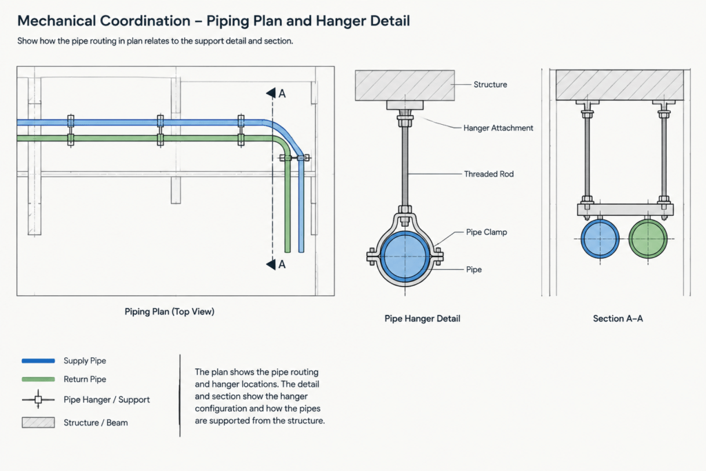
A pipe hanger detail is most useful when its purpose is clear within the drawing set. Use a consistent detail title, identifier, and reference method so readers can connect a plan, section, or piping layout to the supporting detail. Any project-specific notes should be separated from generic CAD geometry and reviewed by the responsible design professional.
Related drawing topics include piping CAD blocks, mechanical equipment layouts, section details, legends and abbreviations, layer standards, and annotation workflows. These references help establish whether the hanger detail is being used as a visual symbol, a typical documentation detail, or part of a coordinated support drawing package.
Engineering and Project Verification
The presence of a hanger assembly in a DWG does not establish its suitability for a particular pipe or supporting structure. The final documentation should be checked against the project design criteria, applicable requirements, manufacturer information, and the responsible disciplines. Avoid adding unverified dimensions, attachment descriptions, or performance claims to the drawing.
Frequently Asked Questions
What is a pipe hanger detail in an AutoCAD drawing?
It is a drafted representation of a support arrangement used to communicate how piping relates to hanger components and nearby construction. Depending on the file, it may function as a reusable CAD block, a typical detail, or reference linework.
Should the DWG be inserted without modification?
No. First confirm the source units, scale behavior, layers, text styles, lineweights, and plot appearance. Rename or remap layers only through the project’s established CAD workflow, while retaining an unchanged source copy for reference.
Can this detail be used as an installation or fabrication instruction?
A generic CAD detail should not automatically be treated as a fabrication or installation document. Project conditions and engineering requirements must be reviewed before it is issued for construction-related use.
What should be checked after importing the drawing?
Check that all objects are visible, text has not shifted, linetypes display properly, external references or fonts are not missing, and the detail appears correctly in both model space and the intended sheet documentation.
How does a pipe hanger detail relate to a piping plan?
The plan shows routing and general system relationships, while a detail can clarify support geometry or drawing intent at a referenced condition. Consistent callouts and detail identifiers connect the two views.












Leave a Reply
You must be logged in to post a comment.