
A zonal control valve detail DWG helps document how a valve and its associated connections are represented within a coordinated system drawing. Depending on the project, the detail may support HVAC, plumbing, or fire protection documentation. The system context should always be confirmed rather than inferred from the file name alone.
Use the downloadable drawing as a CAD reference that can be reviewed and adapted to the conventions of the host project. Before placing it on a sheet, compare its geometry, notes, connection points, and graphic scale with the applicable plans, schematics, specifications, and equipment information.
Discover a high-quality **Zonal Control Valve Detail DWG file** perfect for your engineering and architectural projects. This CAD block provides comprehensive details of a zonal control valve, including its dimensions, connections, and installation layout. Ideal for HVAC, plumbing, and fire protection system designs, this file streamlines your workflow and ensures accuracy in your drawings. Fully compatible with AutoCAD and other leading CAD software, this DWG file allows for easy modification and integration into your existing plans. Enhance your project efficiency with this essential Zonal Control Valve Detail today.
Please log in or register to download this file.
What to Review in the Valve Detail
A detail drawing can communicate more than the outline of a valve. It may also show connection geometry, dimensions, annotations, orientation, and the surrounding installation layout. Review what is actually present in the DWG before deciding how it should be used.
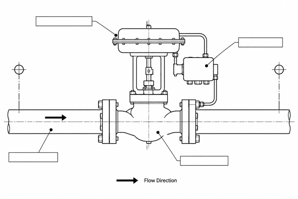
- Drawing views: Identify whether the file contains a plan, elevation, schematic representation, installation detail, or a combination of views.
- Connection points: Check where piping or related system lines are intended to meet the assembly.
- Dimensions: Confirm that displayed dimensions correspond to the specified equipment and project documentation.
- Annotations: Review labels, abbreviations, leaders, and notes for consistency with the project legend.
- Orientation: Determine whether directional symbols, flow indications, or access relationships are shown.
- CAD organization: Inspect layers, line types, lineweights, text styles, blocks, and drawing units before insertion.
System Context and Drawing Coordination
The term zonal control valve can be used in different building-system contexts. Its intended function and surrounding components should be established from the project documents. A symbol or detail used for one discipline should not automatically be treated as interchangeable with another.
Coordinate the detail with the relevant system plan and diagram. A plan establishes location, while a schematic or riser can clarify system relationships. The enlarged detail can then communicate connection arrangement, identification, and installation-related information that would be difficult to read at the plan scale.
Suggested CAD Workflow
- Open and inspect: Review the full file before copying geometry into a production drawing.
- Confirm units and scale: Compare the source drawing settings with the destination file without assuming they match.
- Check references: Look for missing external references, fonts, line types, or other dependencies.
- Map layers: Move objects to approved project layers while preserving useful object separation.
- Standardize graphics: Align text, leaders, hatches, lineweights, and symbols with the project CAD standard.
- Verify equipment information: Compare the drawing with the selected equipment data and current design documents.
- Coordinate placement: Check the detail against plans, diagrams, equipment layouts, and other discipline backgrounds.
- Record revisions: Use the project revision process when notes, geometry, or identifiers are changed.
Related Drawing References
This detail is most useful when viewed alongside related CAD references such as valve symbols, piping schematics, fire protection diagrams, equipment layouts, drawing legends, and annotation guides. These related drawing types help distinguish a simplified plan symbol from an enlarged installation detail and improve consistency across the document set.

Important Verification Note
A reusable CAD detail is a drafting resource, not confirmation that an arrangement is correct for every application. Final geometry, component selection, accessibility, notes, and system requirements should be checked against the project design, equipment documentation, and applicable requirements by the responsible design professional.
Frequently Asked Questions
What is a zonal control valve detail DWG used for?
It is used as a CAD reference for documenting a valve, its connections, dimensions, annotations, and installation layout within a larger drawing set. Its exact role depends on the system and project documentation.
Can the DWG be inserted directly into a project drawing?
Inspect it before insertion. Drawing units, layers, text styles, line types, scale, and connection geometry may need to be aligned with the destination file and office standards.

Is the detail limited to one building system?
The source identifies possible use in HVAC, plumbing, and fire protection design. Confirm the intended discipline from the drawing content and project documents because terminology and graphic conventions can vary.
Should displayed dimensions be treated as universal?
No. Dimensions should be compared with the selected equipment information and the coordinated project design. Do not scale geometry from the drawing when a verified dimension or manufacturer document is required.
What other drawings should be checked with this detail?
Review the applicable plans, schematics, risers, equipment layouts, legends, schedules, and discipline coordination backgrounds. Together, these documents establish location, system relationships, identification, and drawing context.












Leave a Reply
You must be logged in to post a comment.