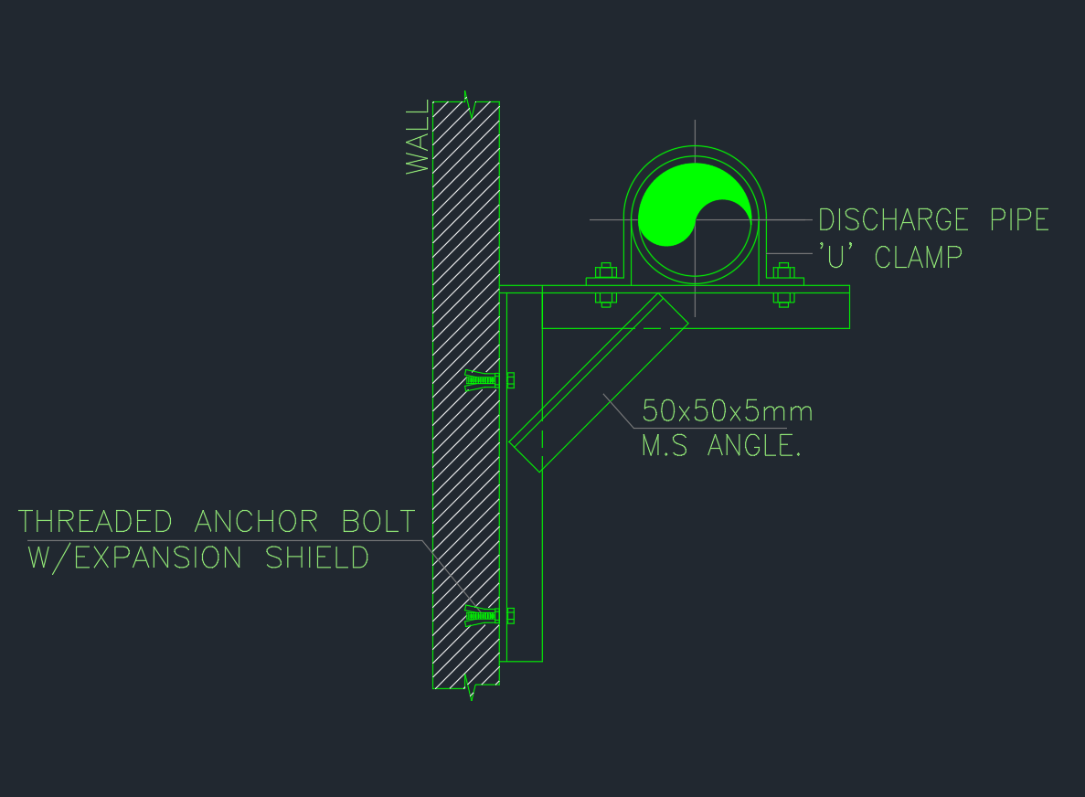
A pipe support through-wall CAD detail helps document how a pipe is routed, supported, and coordinated where it intersects a wall assembly. The detail can serve as a drafting reference for plan sets that require a clearer view than a plan or elevation alone can provide.
Use the existing DWG content as a starting point rather than a project-ready specification. Wall construction, pipe material, support type, movement requirements, sealing method, and applicable project criteria should be confirmed before the detail is issued for construction.
Discover the **typical installation details of pipe support through-wall** with this comprehensive DWG file and CAD Block, designed for engineers and architects working on piping systems. This downloadable resource provides precise and standardized installation details for supporting pipes that pass through walls, ensuring structural integrity and compliance with industry standards. Perfect for HVAC, plumbing, and industrial projects, the CAD Block is fully compatible with AutoCAD and other leading CAD software, allowing seamless integration into your construction drawings. Streamline your design process with this essential, ready-to-use pipe support detail for accurate and professional results.
Please log in or register to download this file.
What a Through-Wall Pipe Support Detail Communicates
A typical detail should make the relationship between the pipe, wall opening, sleeve or penetration treatment, and support components easy to interpret. Its purpose is not only to show geometry, but also to clarify which elements are being supported and how the penetration coordinates with the surrounding construction.
The support should be distinguishable from the wall penetration itself. A sleeve, seal, escutcheon, fire-resistive system, waterproofing component, or other opening treatment may have a separate function and should not automatically be interpreted as carrying the pipe load.

Key Items to Review in the CAD Drawing
- Pipe path: Confirm that the pipe centerline and direction of travel are visually clear.
- Wall assembly: Identify whether the wall is shown schematically or represents a defined architectural or structural condition.
- Support relationship: Make clear whether the support connects to the wall, nearby structure, framing, or another approved supporting element.
- Penetration components: Distinguish the opening, sleeve, seal, trim, and support hardware where those items are part of the design.
- Clearance and movement: Coordinate space for installation, movement, insulation, maintenance, and adjacent systems without assuming the downloaded geometry fits every condition.
- Annotations: Replace generic notes with project-specific material, specification, and coordination references where required.
Using the DWG in a Drawing Set
Before inserting the block, check its units, scale, layer names, lineweights, text style, and linetypes against the project CAD standard. Place editable notes and dimensions on appropriate annotation layers so the detail remains legible at its intended plotted scale.
Give the detail a consistent title and reference designation, then coordinate its callout with the relevant plan, section, or elevation. If several wall types or support conditions occur, avoid using one generic detail for unlike assemblies. Separate details or clearly identified variations may reduce ambiguity.
Coordination With Related Drawings
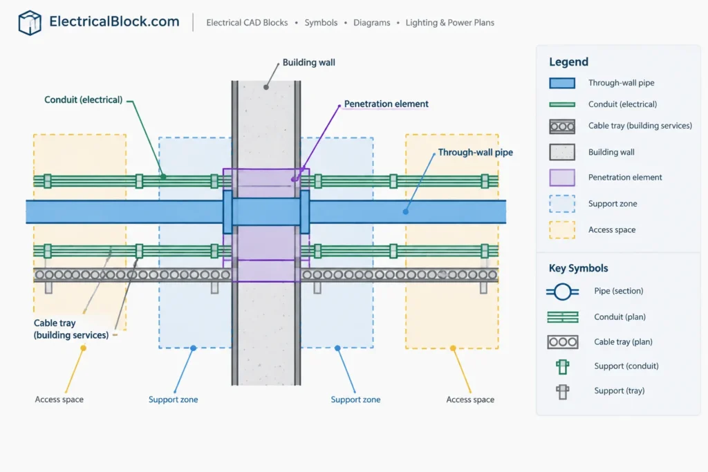
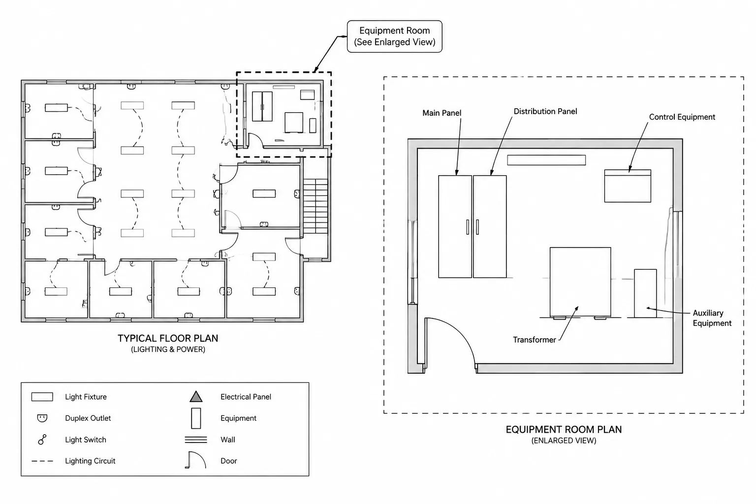
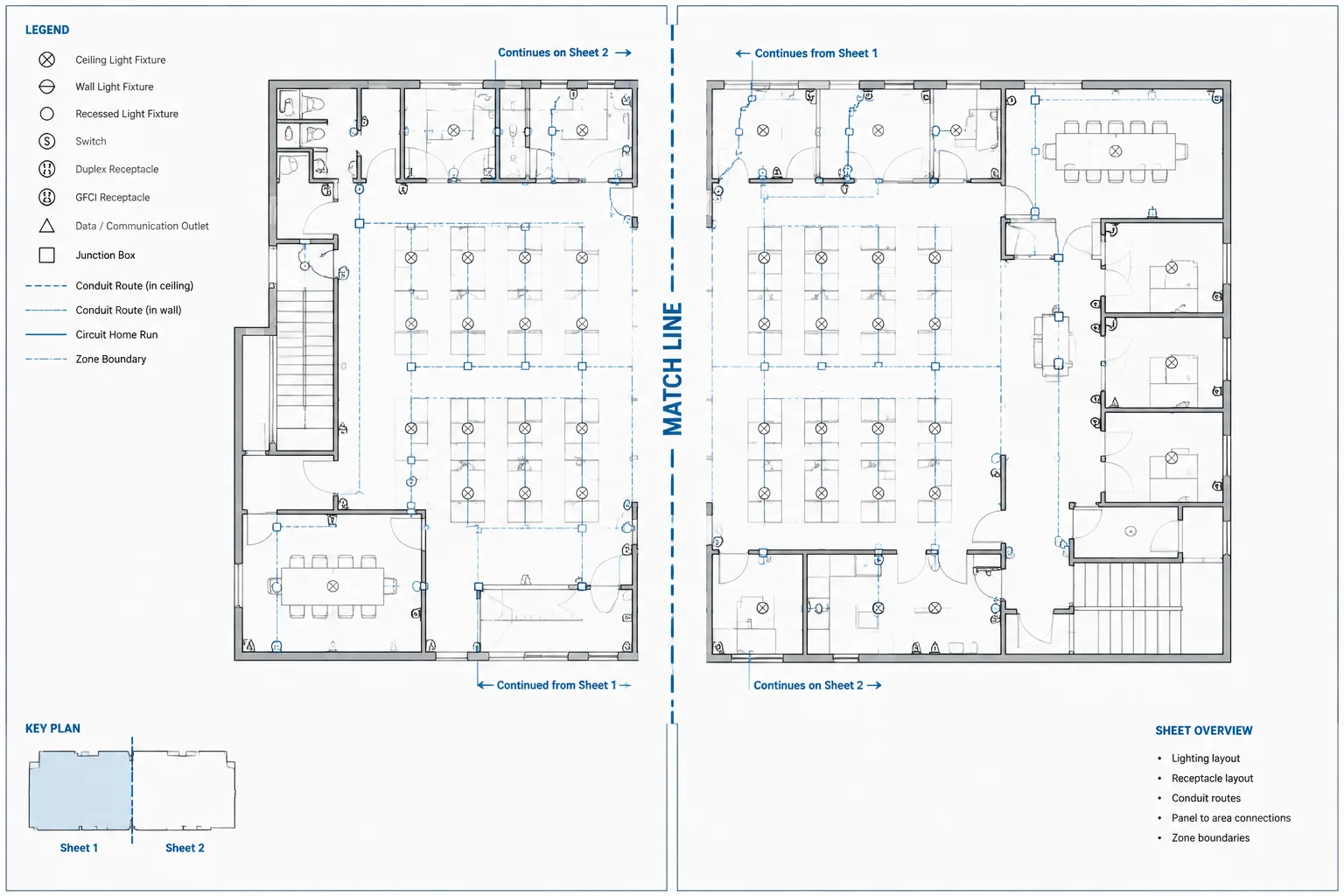
Through-wall conditions often require review across architectural, structural, mechanical, plumbing, fire-protection, and electrical documentation. For electrical drafting, the same coordination principles can inform conduit penetration details, equipment-room layouts, sleeve schedules, and cable-routing drawings, although the components and project requirements may differ.
Related drafting references include CAD layer conventions, conduit and cable documentation, equipment layout coordination, drawing legends, and section-detail callouts. Reviewing these topics together helps keep symbols, notes, and cross-references consistent throughout the drawing set.

Drawing Review Checklist
- Confirm that the block uses the project drawing units and insertion scale.
- Verify that the wall condition matches the location referenced by the plan.
- Check that support components are graphically distinct from penetration seals and finishes.
- Coordinate insulation, access, adjacent services, and required movement.
- Review notes for conflicts with specifications and discipline-specific details.
- Remove unused layers, duplicate geometry, and unrelated source-file content.
- Have the final support and penetration arrangement reviewed by the responsible design professionals.
A typical CAD detail is a documentation aid. It does not establish structural adequacy, code compliance, fire rating, waterproofing performance, or suitability for a particular installation without project-specific verification.
Frequently Asked Questions
What is a pipe support through-wall CAD detail?
It is a section or installation drawing that illustrates the relationship between a pipe, its support, the wall opening, and associated penetration components. It is commonly used to supplement plans and elevations.
Can the downloaded detail be inserted directly into construction drawings?
It can be used as a drafting reference, but its units, scale, layers, notes, geometry, and wall condition should be checked first. Project-specific design review is still required.
Is the wall sleeve the same as the pipe support?
Not necessarily. A sleeve typically defines or protects the penetration, while a support transfers or restrains loads. Their functions should be shown and specified separately unless the project design establishes otherwise.
What CAD elements should be edited after insertion?
Common review items include layer assignments, text styles, lineweights, dimensions, leaders, material labels, detail references, and notes. Unused source layers and duplicate objects should also be removed.
Can this detail be used for conduit penetrations?
It may help illustrate general drafting and coordination concepts, but piping and electrical conduit systems can require different supports, fittings, seals, and documentation. Use a discipline-appropriate detail for the final design.
Why should penetration and support requirements be coordinated separately?
The wall opening may need sealing, weather protection, fire-resistive treatment, acoustic treatment, or architectural finishing, while the support addresses load and movement. Treating these as separate design functions helps prevent unclear documentation.










Leave a Reply
You must be logged in to post a comment.