
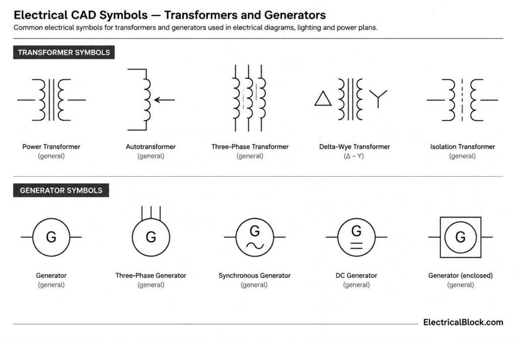
This transformer and generator symbols DWG collection supports electrical drafting workflows for schematics, equipment layouts, and single-line diagrams. The downloadable CAD blocks provide reusable graphics that can be incorporated into a project drawing and coordinated with its legend, layers, labels, and equipment references.
Before using any symbol, compare its meaning and appearance with the conventions established for the project. Electrical symbols can vary among design firms, facility owners, utilities, and drawing types, so a block should not be treated as a substitute for the project legend or documentation requirements.
Download the high-quality DWG file featuring detailed Transformers Generators Symbols for your electrical CAD projects. This comprehensive CAD Block provides a variety of standard transformer and generator symbols, ideal for creating accurate electrical schematics, layouts, and single-line diagrams. Perfect for electrical engineers, designers, and architects, these symbols ensure clarity and consistency across your drawings. Compatible with AutoCAD and other popular CAD software, the DWG file allows easy integration into your existing projects, streamlining your workflow and enhancing design precision. Use these symbols for efficient planning and documentation of electrical systems.
Please log in or register to download this file.
Using Transformer and Generator Symbols in Electrical Drawings
Transformer and generator symbols are graphical references rather than complete equipment specifications. In a schematic or single-line diagram, they help communicate where power conversion or generation functions occur and how those functions relate to feeders, distribution equipment, protective devices, and connected loads. Equipment ratings, operating characteristics, and installation details should be documented separately through labels, schedules, notes, or approved project data.
Choose the Symbol by Drawing Purpose
A symbol used in a single-line diagram may emphasize an electrical relationship, while a symbol used in an equipment layout may represent location or identification. These are different documentation purposes. Do not assume that a schematic symbol represents the physical footprint, clearance, connection arrangement, or installation geometry of actual equipment.
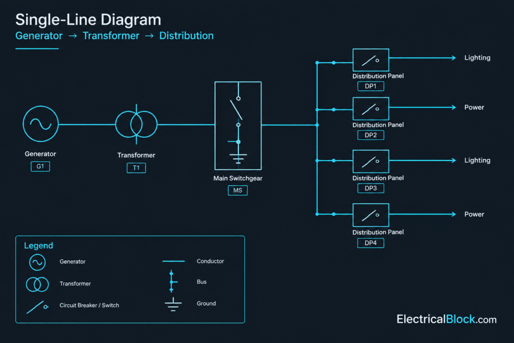
- Single-line diagrams: Use symbols to show the logical path through generation, transformation, and distribution components.
- Electrical schematics: Coordinate each block with conductors, terminals, control references, and explanatory notes as required by the drawing set.
- Equipment layouts: Use verified manufacturer or project geometry when physical size and placement matter.
- Legends: Identify the meaning of each symbol so readers do not have to infer its function from appearance alone.
Review the DWG Blocks Before Placement
Inspect downloaded blocks in a controlled working file before adding them to a live project. Check the insertion point, orientation, layer assignment, linework, text objects, attributes, and block name. Also confirm that the drawing units and scale behavior match the destination file. This review helps prevent misplaced geometry, inconsistent plotting, duplicate block definitions, and unexpected annotation changes.
If a destination drawing already contains a block with the same name, inserting another definition may produce unintended results. A clear naming convention can distinguish office-library symbols from project-specific or externally supplied blocks. Keep edits within the block definition deliberate, because a definition change may affect every instance using that block.
Coordinate Symbols With Drawing Data
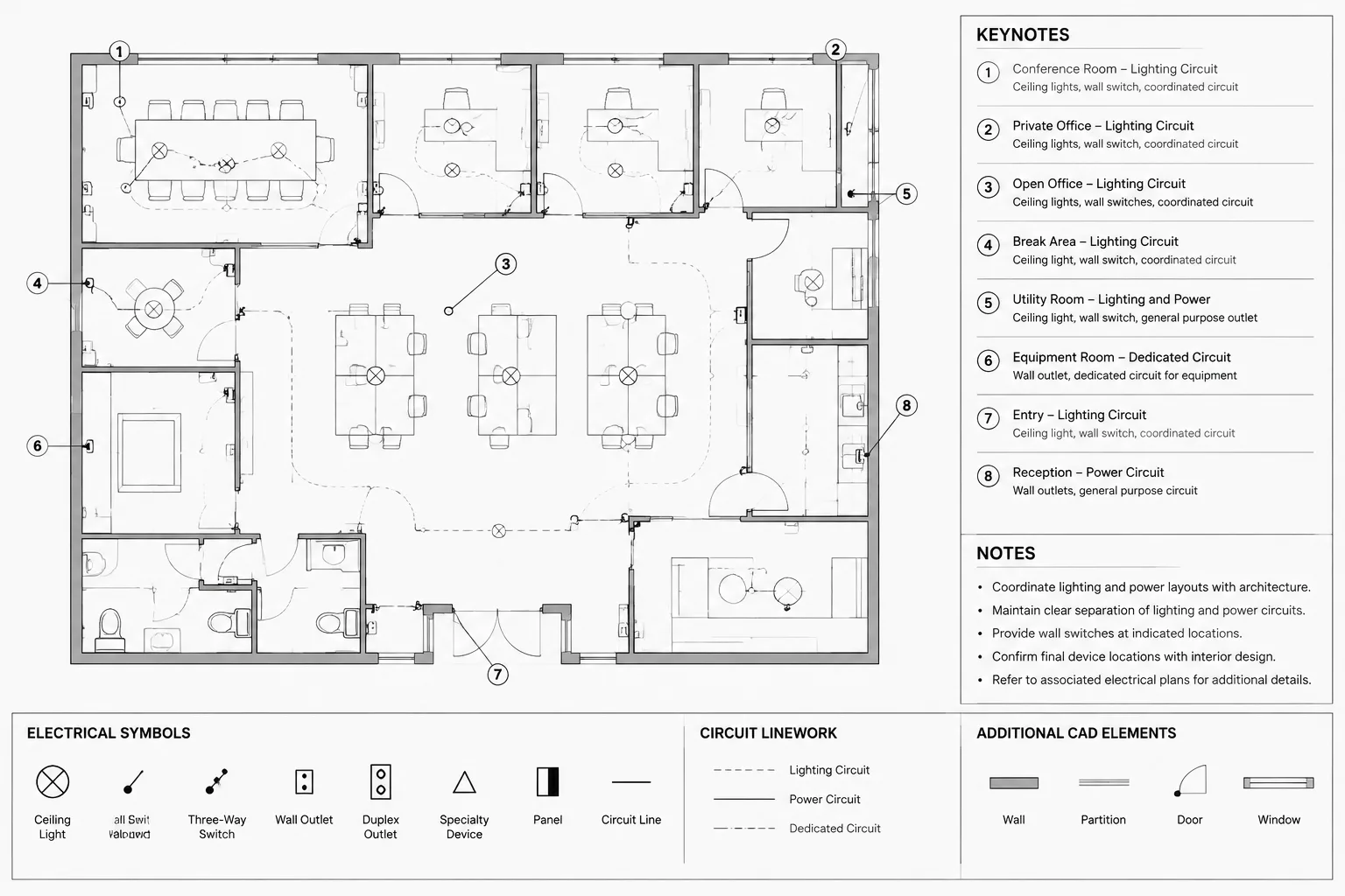
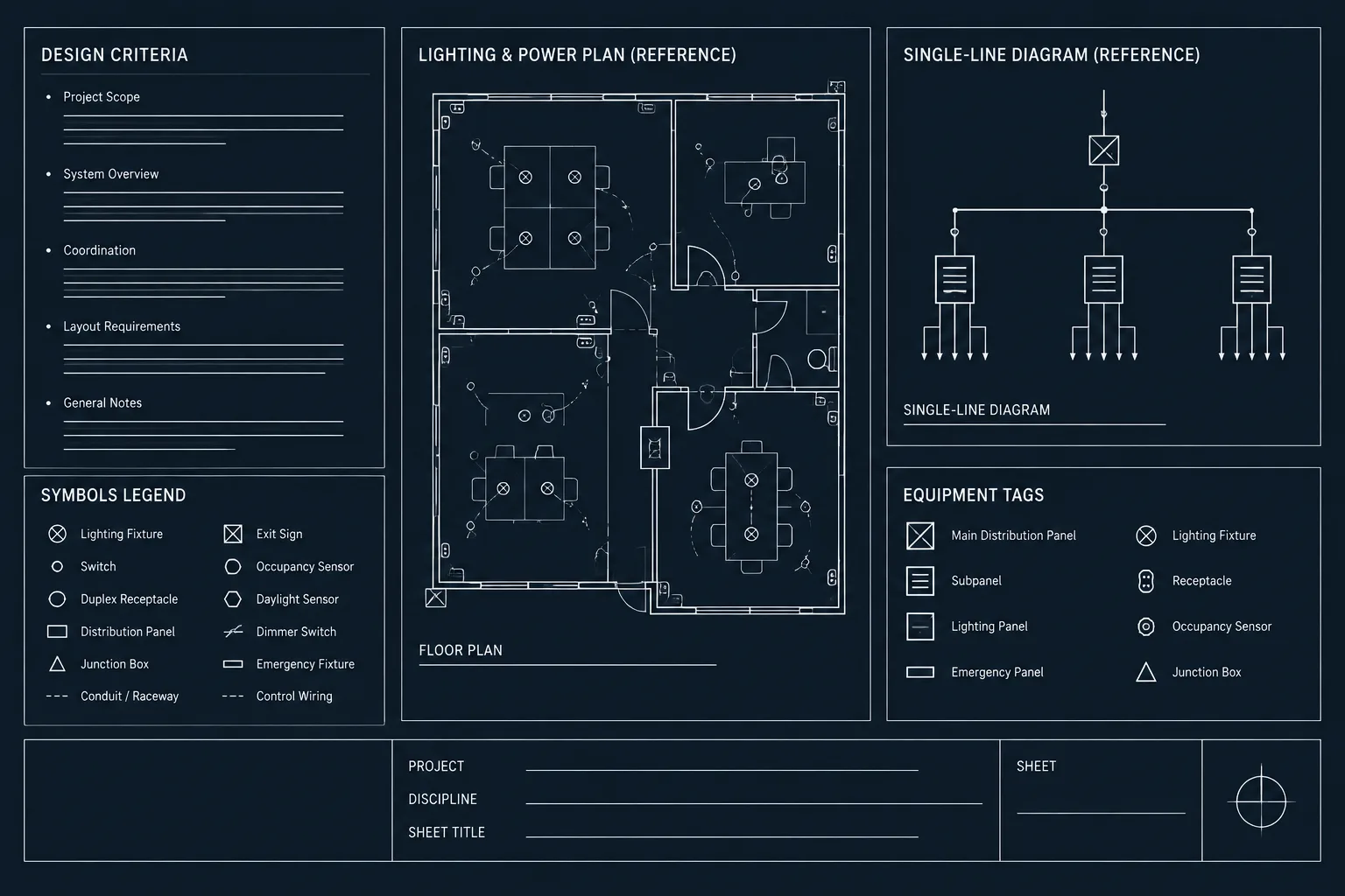
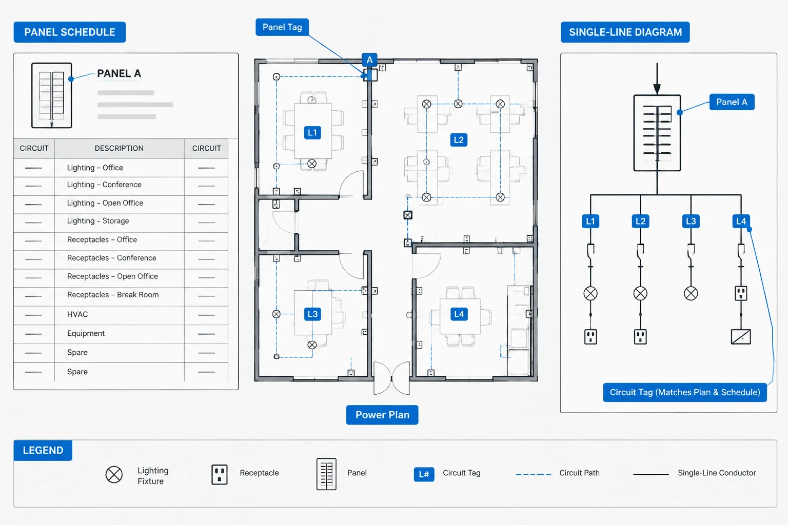
A useful electrical symbol should connect visually and logically with the rest of the documentation. Align connection points cleanly with diagram lines, maintain readable spacing, and avoid crossing text or conductors through the symbol. Where identification is needed, use consistent equipment tags and coordinate them with schedules, notes, and related sheets.
- Place symbols on appropriate electrical or annotation layers.
- Use consistent line types, lineweights, colors, and plotting behavior.
- Keep equipment identifiers legible at the intended plotted scale.
- Confirm that block attributes display correctly after insertion.
- Remove redundant geometry and unused definitions from the working copy when appropriate.
- Include the selected symbols in the project legend when their meaning is not already established.
Related Electrical Drafting Topics
These blocks are most useful when considered alongside single-line-diagram concepts, electrical legends, panel and distribution drawing practices, cable and conduit documentation, equipment layouts, and CAD layer management. Reviewing those related topics can help a drafter maintain consistent graphic language across an entire electrical drawing set.
Quality-Control Considerations
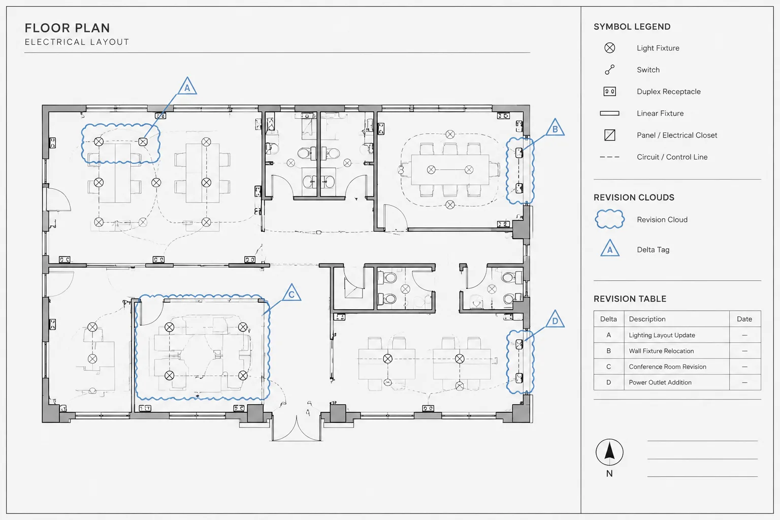
CAD compatibility does not guarantee that a symbol automatically satisfies a particular owner, authority, or project standard. After import, review the geometry and intended meaning within the target software and drawing template. Final symbol selection, equipment data, and system relationships should be checked by the responsible project professional before issue.
Frequently Asked Questions
What does the DWG file contain?
The source describes a collection of transformer and generator symbols intended for electrical CAD drawings, including schematics, layouts, and single-line diagrams. Use the preserved download control on this page to access the file.
Are these symbols physical equipment footprints?
Not necessarily. A schematic symbol usually communicates equipment function or system relationship. Physical layout work should use verified project or manufacturer geometry when dimensions, connection locations, or clearances matter.

Can the blocks be used in a single-line diagram?
Yes. Place the selected symbols within the diagram’s power-flow structure, then coordinate them with equipment tags, conductor lines, notes, and the project legend.
What should be checked after importing the DWG?
Review units, insertion points, layers, block names, attributes, text behavior, linework, orientation, and plotted appearance. Also check for conflicts with existing block definitions in the destination drawing.
Do transformer and generator symbols have one universal appearance?
No single graphic convention applies to every organization or drawing type. Confirm the required symbol convention against the project’s legend, client requirements, and approved documentation practices.
Should electrical ratings be added to the block?
Only add ratings or equipment data that come from verified project information. Depending on the drawing workflow, the data may be shown as attributes, adjacent labels, notes, or coordinated schedule entries.


Leave a Reply
You must be logged in to post a comment.