
This Circuit Symbols Blocks DWG provides a reusable reference for electrical and electronic drafting workflows. Instead of redrawing common schematic elements, designers can work from organized CAD blocks while developing diagrams, wiring layouts, and control-panel documentation.
The file is intended for use with AutoCAD and other compatible CAD applications. Before placing symbols in a deliverable, review their appearance, orientation, layer behavior, and annotation requirements against the project’s drawing conventions.
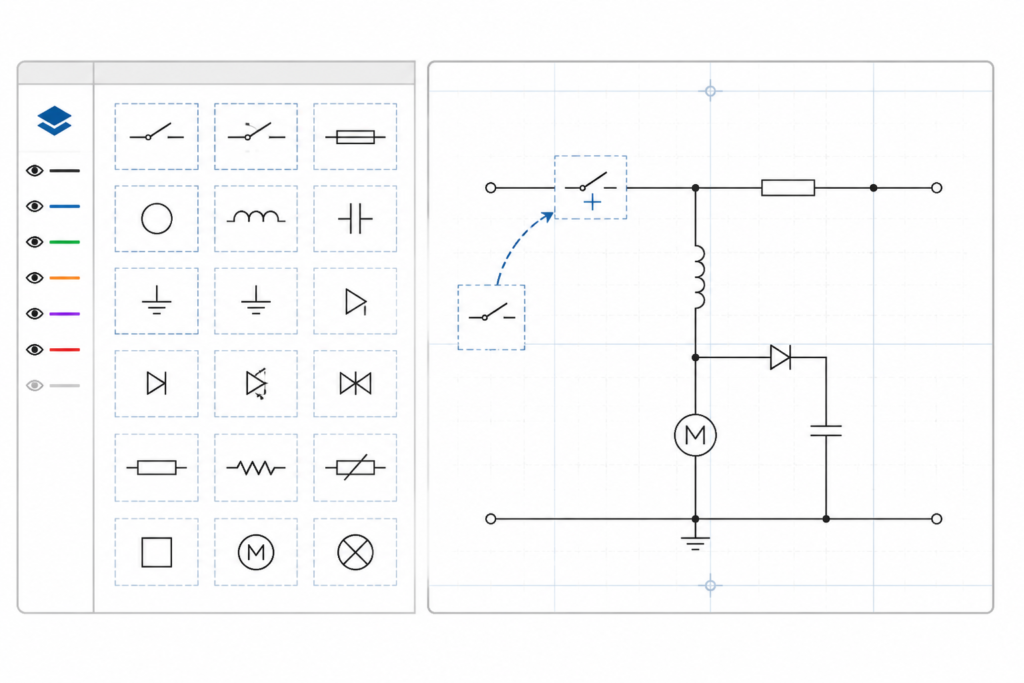
Discover a comprehensive DWG file featuring meticulously designed Circuit Symbols Blocks Stages, perfect for electrical and electronic CAD projects. This CAD Block collection includes a wide range of standardized circuit symbols, making it ideal for professionals and students working on schematic diagrams, wiring layouts, and control panel designs. The file is fully compatible with AutoCAD and other popular CAD software, ensuring seamless integration into your workflow. Enhance your electrical drawings with these high-quality, ready-to-use circuit symbol blocks and streamline your design process. Perfect for engineers, architects, and designers seeking reliable and precise CAD resources.
Please log in or register to download this file.
How to use circuit symbol blocks in CAD drawings
Circuit symbol blocks are most useful when they are treated as drafting components rather than as a substitute for design review. A symbol communicates an electrical function or device category, while the surrounding drawing establishes connections, references, labels, and project-specific meaning.
Typical drafting applications
- Schematic diagrams: Place symbols to develop readable circuit relationships and signal paths.
- Wiring layouts: Use consistent block geometry to support clearer connection and routing documentation.
- Control-panel drawings: Arrange device symbols with labels and references that match the panel documentation.
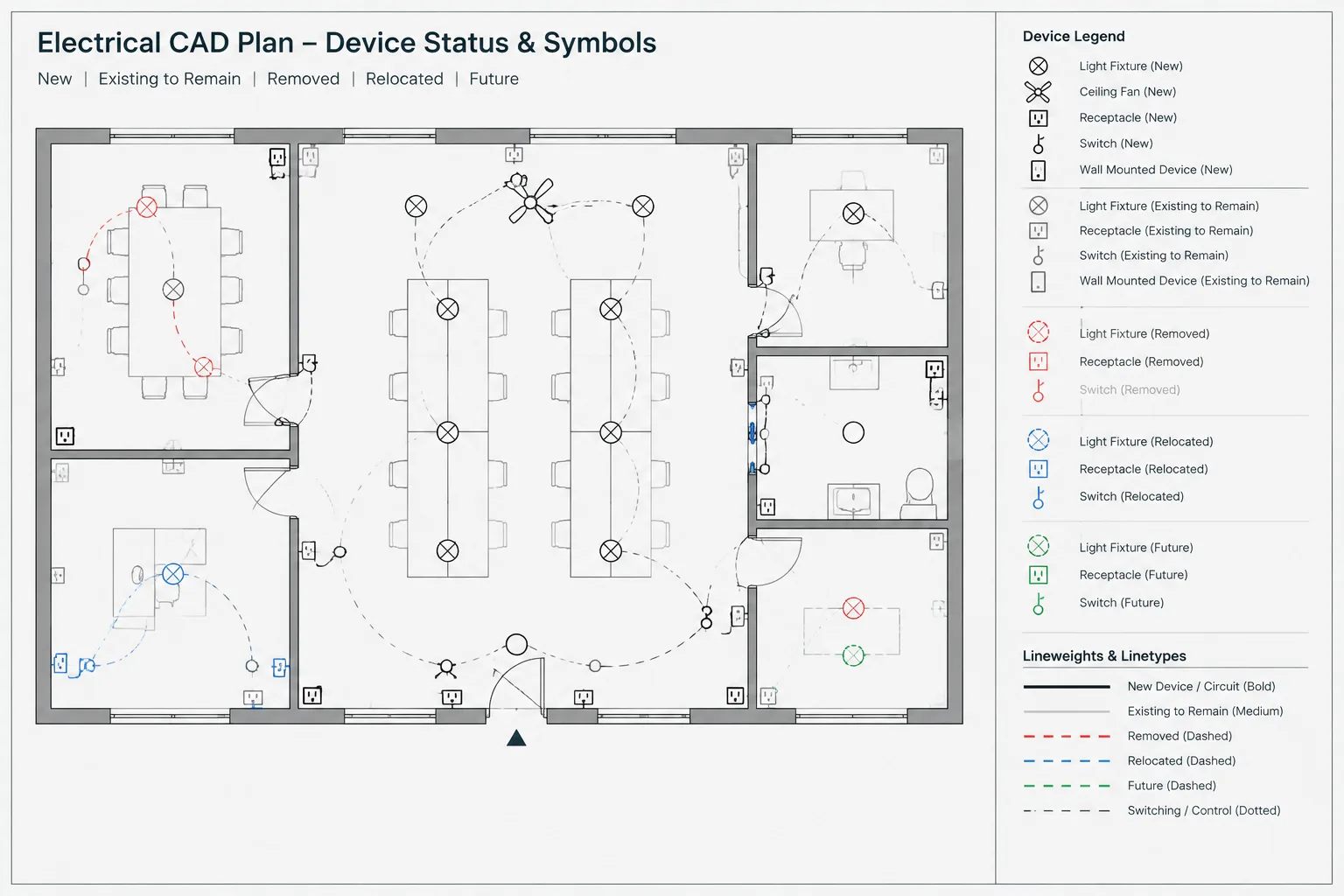
- Electrical legends: Compare selected symbols with the project legend so the drawing uses consistent graphic language.
Practical CAD checks
- Confirm that inserted blocks use the intended insertion point and orientation.
- Check layer assignments, lineweight behavior, text visibility, and scaling within the drawing environment.
- Keep symbol labels and device references coordinated with the associated schedules and documentation.
- Inspect the final plotted or exported drawing for overlapping graphics, missing attributes, and unclear connection points.
These checks help preserve consistency when circuit symbols are reused across schematic sheets, wiring documentation, and equipment layouts. They also make the block collection easier for teams to review and maintain.
Frequently asked questions
What is included in this Circuit Symbols Blocks DWG?
The source describes a collection of circuit symbol blocks for electrical and electronic CAD projects, including symbols intended for schematic diagrams, wiring layouts, and control-panel designs.
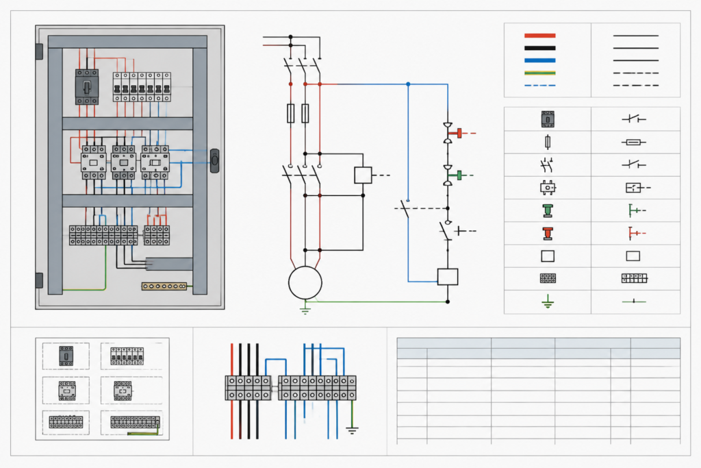
Can the file be used with AutoCAD?
Yes. The source identifies the file as compatible with AutoCAD and other popular CAD software. Users should still confirm compatibility with their specific application and drawing setup.
Are these blocks a replacement for an electrical design review?
No. Blocks provide reusable drawing geometry and help organize documentation, but they do not verify circuit operation, equipment selection, code compliance, or installation requirements. Design decisions should be reviewed by the responsible qualified professionals.

How should symbols be checked before issue?
Review the symbol appearance, orientation, layers, labels, connection points, and plotted output. Compare them with the project legend and documentation standards before including them in an issued drawing.
Who may find this CAD resource useful?
Engineers, architects, designers, CAD technicians, and students may use the collection as a drafting reference for electrical and electronic documentation.










Leave a Reply
You must be logged in to post a comment.