
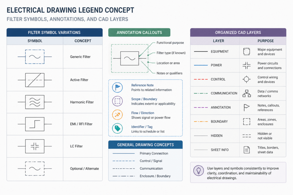
Electric filter symbols help communicate how filtering functions are represented within an electrical schematic or drawing. This resource is intended for designers, drafters, students, and reviewers who need reusable CAD content for documenting filter-related components and circuit relationships.
Before placing a symbol, compare it with the project legend and drafting conventions. Symbol appearance, annotation practice, and layer organization can vary between offices and drawing packages, so a CAD block should support the drawing standard rather than replace it.
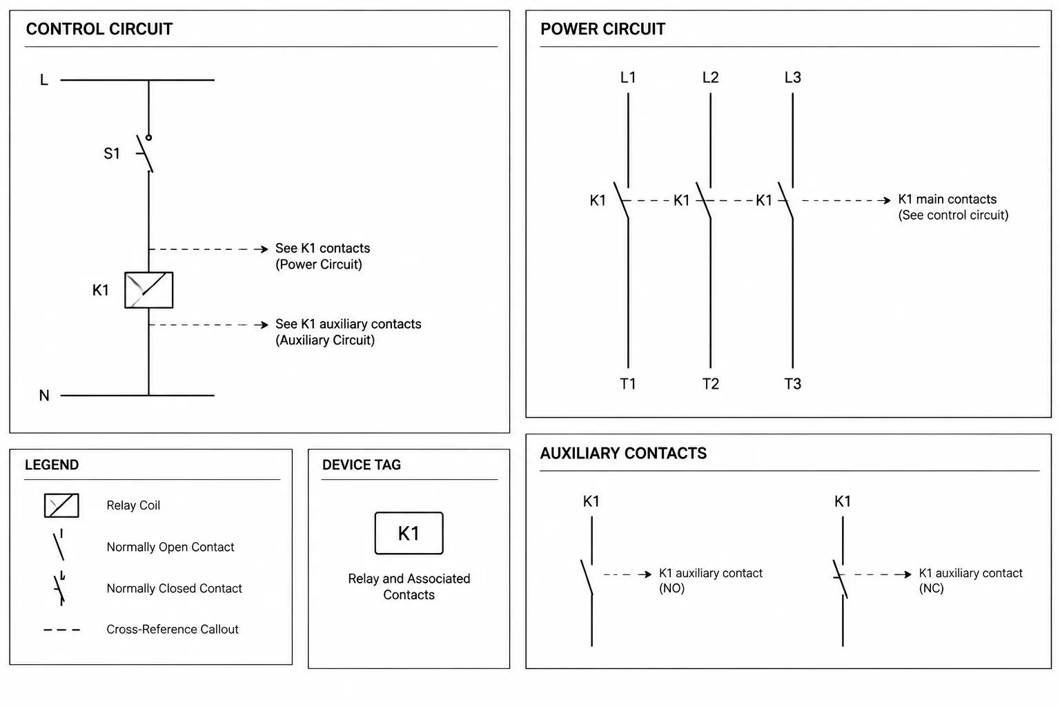
Discover a comprehensive collection of Electric Filter Symbols in DWG format, ideal for professionals and students working on electrical design projects. This CAD Block file includes a wide range of standardized electric filter symbols used in circuit diagrams, making it easy to enhance your AutoCAD drawings with accurate representations. Perfect for use in schematic diagrams, electrical layouts, and engineering documentation, these symbols ensure clarity and consistency in your projects. The DWG file is fully compatible with AutoCAD and other CAD software, allowing seamless integration into your workflow and saving valuable design time.
Please log in or register to download this file.
How to use electric filter symbols in CAD drawings
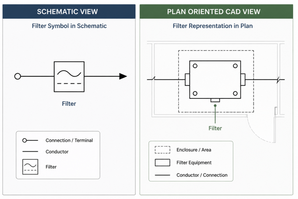
Filter symbols are typically used to show a functional part of a circuit rather than to communicate every physical construction detail. Their meaning is clearest when the symbol is connected to the surrounding conductors, devices, signal paths, or equipment shown on the same drawing.

Common drawing applications
- Schematic diagrams: Show the filter in relation to circuit elements and indicate the intended flow or connection path.
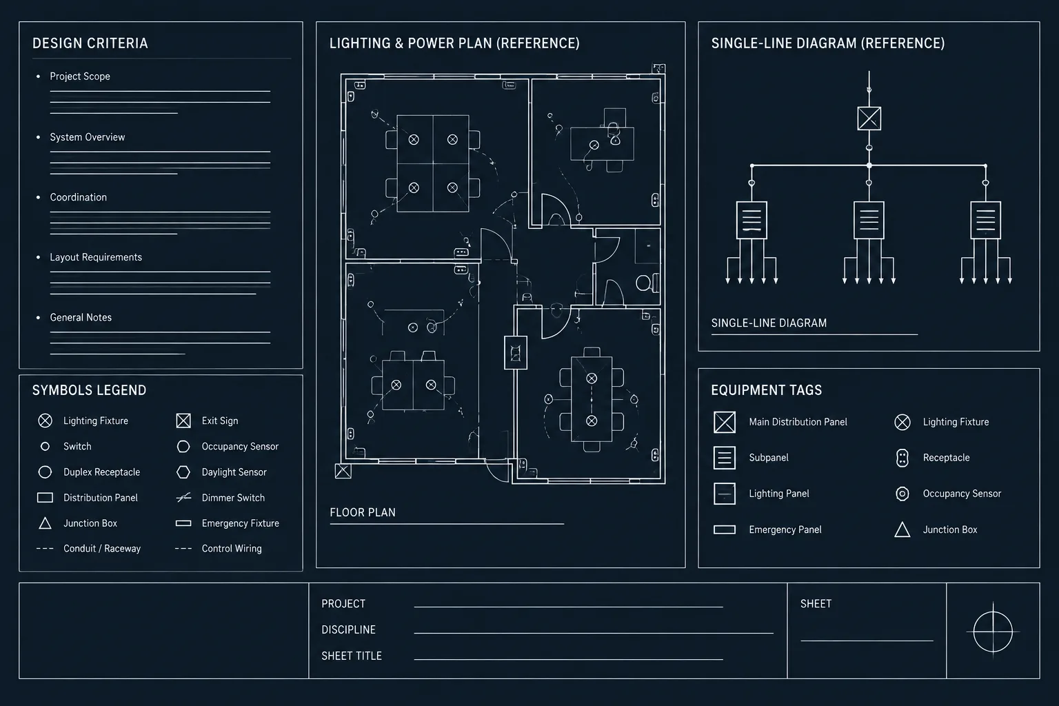
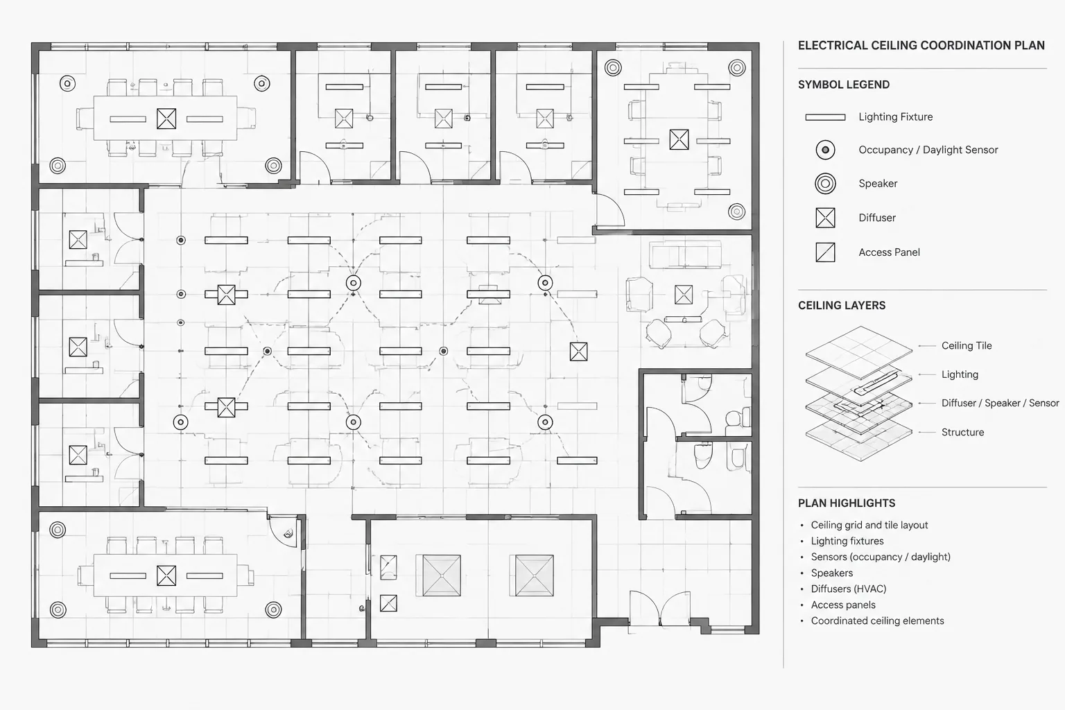
- Electrical layouts: Coordinate the filter symbol with equipment references, room or system identifiers, and other plan information when the drawing requires a physical location.
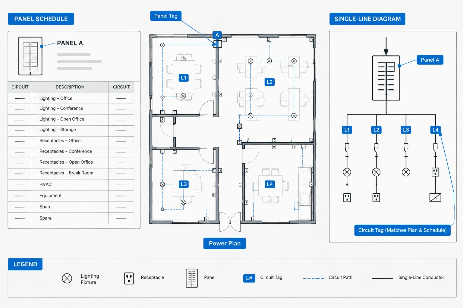
- Single-line and functional diagrams: Use the symbol to simplify a system while preserving the relationship between major devices.
- Legends and notes: Define the symbol meaning when the project uses a custom convention or when several filter types appear in the same document.
CAD coordination checklist
- Confirm that the block uses the intended insertion orientation and scale behavior for the drawing.
- Review layer assignments so visible geometry, annotation, and reference information can be controlled consistently.
- Check linework, text style, insertion point, and block naming before adding the symbol to a shared library.
- Keep the symbol visually distinct from nearby conductors and equipment graphics.
- Compare the placed block with the project legend and the engineering information supplied for the actual system.
Relationship to related electrical drawing topics
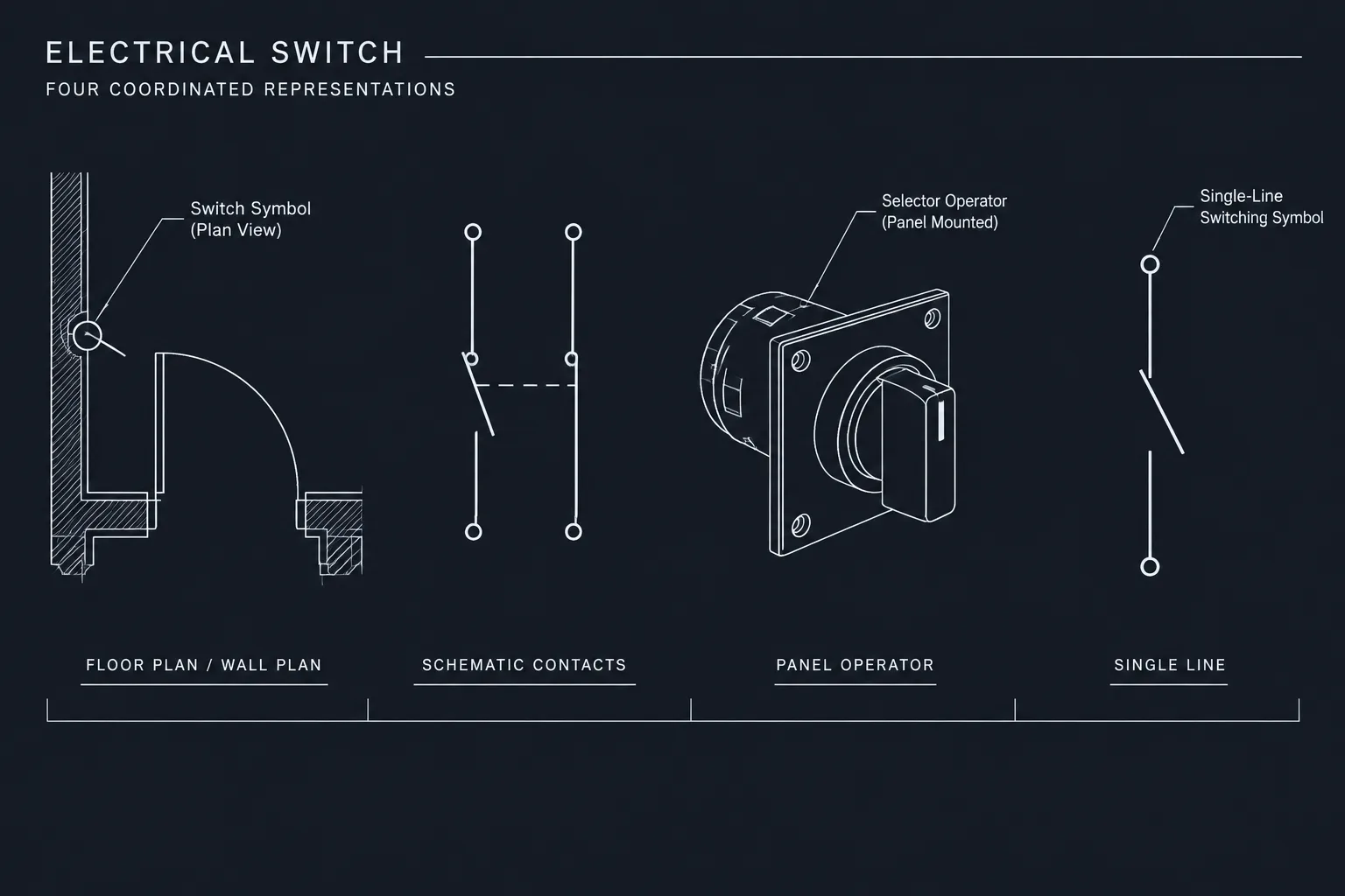
Electric filter symbols are most useful when considered alongside electrical symbols and legends, CAD layer standards, single-line diagrams, panel documentation, and cable or conduit drafting. Those related topics explain how a symbol is identified, grouped, connected, and reviewed across a complete drawing set. A filter symbol alone does not establish circuit performance, installation requirements, ratings, or design compliance.
Reference use and review
Use the DWG resource as a drafting aid and visual reference. After insertion, inspect the block in the target drawing environment and verify that its graphic convention agrees with the project requirements. Engineering review is still necessary to confirm that the documented filter represents the intended equipment or circuit function.
Frequently asked questions
What are electric filter symbols used for?
They represent filtering functions or filter-related components in electrical schematics, functional diagrams, legends, and selected layout drawings.
Can these DWG blocks be used in AutoCAD drawings?
The source content identifies the resource as a DWG file intended for AutoCAD and other CAD software. Always inspect the imported block and confirm compatibility with the target drawing setup.
Should a filter symbol be treated as an installation detail?
No. A symbol communicates drawing information at a selected level of detail. It does not by itself define equipment ratings, wiring requirements, physical construction, or installation compliance.
Why should the project legend be checked?
Electrical symbols can vary by office standard, discipline, project, or drawing type. The legend provides the controlling interpretation for the specific drawing set.
What should be reviewed after inserting a CAD block?
Review the block’s orientation, layer behavior, insertion point, linework, annotation, and relationship to connected circuit graphics. Confirm that the result remains legible at the intended drawing scale.
Leave a Reply
You must be logged in to post a comment.