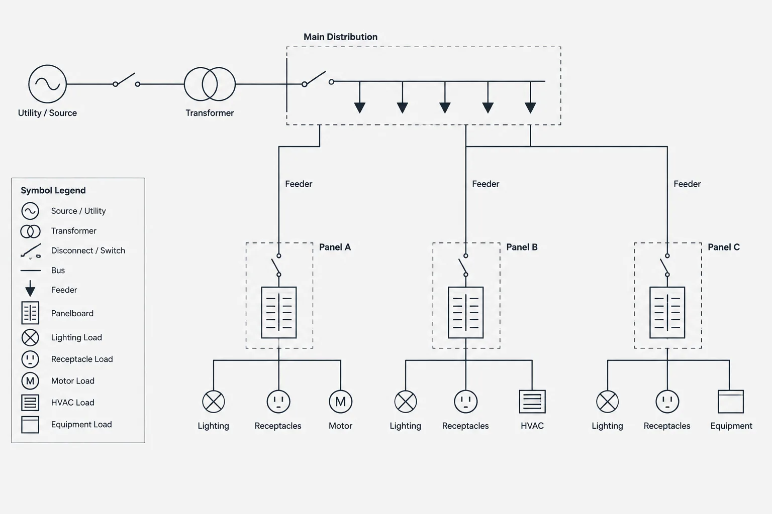
A readable single-line diagram depends on more than correct connectivity. Its visual hierarchy must help the reader recognize where power originates, how it passes through distribution equipment, and where each feeder terminates.
This drafting reference explains how to structure that hierarchy in CAD while keeping symbols, annotations, continuation references, and related project documents coordinated. It is intended as a documentation guide rather than a substitute for project-specific electrical design or professional review.
A single-line diagram can contain the correct electrical relationships and still be difficult to read. Crowded feeder paths, inconsistent device spacing, unclear continuation points, and poorly placed equipment tags can obscure the intended distribution hierarchy. A strong single-line diagram layout in CAD makes that hierarchy visible before a reviewer begins reading individual ratings or notes.
This guide focuses on graphical organization and documentation workflow. It does not establish equipment ratings, conductor requirements, protection settings, or code compliance. Those project-specific decisions must be verified by the responsible design team.
Begin with the distribution story
Before placing symbols, identify the story the diagram must communicate. Most power-distribution single-lines move through a recognizable sequence:
- Incoming utility, generator, inverter, or other source
- Service or source-side switching and protection
- Main distribution equipment
- Transformers, transfer equipment, and intermediate distribution
- Branch distribution panels or control equipment
- Major connected loads and referenced downstream systems
The drawing does not have to place every project into the same visual arrangement. It should, however, let a reader follow the power path without repeatedly searching across the sheet. Establish the principal path first and add secondary branches afterward.
Choose a consistent reading direction
Many diagrams are easiest to navigate when the primary power flow follows one dominant direction, such as top to bottom or left to right. Mixing directions without a clear reason can make electrically separate branches appear related or make related equipment seem disconnected.
Choose the direction based on the shape of the distribution system and the available sheet area. A tall hierarchy may work well vertically, while a system with several parallel branches may benefit from a horizontal arrangement. Whichever direction is selected, apply it consistently across related diagrams.
Keep upstream and downstream positions predictable
Sources and upstream devices should occupy a visually distinct region from downstream distribution and loads. Predictable positioning helps readers interpret connectivity even before they examine tags. It also makes later additions easier because the drafter knows where each new item belongs in the hierarchy.

Build the diagram around buses and major nodes
Buses, switchboards, panelboards, transfer equipment, transformers, and similar distribution points form the diagram’s structural framework. Place these major nodes before drawing every feeder. This prevents the layout from being controlled by whichever branch happened to be drafted first.
Align equipment with similar functions where practical. For example, downstream panels supplied from the same distribution point can share an alignment, while major mechanical or process loads can occupy a separate area. Alignment does not imply identical electrical characteristics; it simply improves visual comparison.
Use spacing to show relationships
Spacing is a documentation tool. Closely grouping a source, its associated main device, and the equipment it directly serves can reinforce their relationship. Extra space between separate systems can help distinguish normal power, backup power, life-safety distribution, tenant distribution, or other project-defined groupings.
Avoid relying on spacing alone. System boundaries should also be supported by labels, line conventions, notes, or sheet organization appropriate to the project.
Route feeders for traceability
Feeder lines should be easy to trace from one labeled endpoint to another. Whenever possible, use direct paths with a limited number of direction changes. Parallel feeder routes should have enough separation to remain distinguishable after plotting or PDF reduction.
Crossing lines are a common source of ambiguity. A crossing can be mistaken for a connection, particularly when the diagram is viewed at a reduced scale. Improve clarity by rearranging equipment, shifting branches, or using documented continuation references instead of forcing numerous feeders through the same area.
Distinguish connections from crossings
Apply one consistent graphic convention for intentional junctions and another for lines that merely cross. The selected convention should appear in the project legend or drafting standard when its meaning may not be obvious. Do not introduce multiple junction styles simply to solve isolated layout problems.
Avoid unsupported feeder lines
Every displayed feeder should terminate at identifiable equipment, a defined load, or a clear continuation reference. Lines that disappear at a sheet edge or end near a symbol without an explicit connection create uncertainty during review.
Place protective devices where their relationship is clear
Protective and switching device symbols should be positioned so readers can tell which feeder or equipment they belong to. A device placed too close to an adjacent branch may appear to protect the wrong circuit. Consistent symbol orientation and spacing reduce that risk.

Keep device identification and associated data close enough to the symbol to form a clear visual group. When extensive information would overwhelm the diagram, use a coordinated schedule, note, or equipment reference rather than compressing text into the feeder path.
Create a repeatable annotation structure
A single-line diagram often combines equipment names, circuit references, conductor descriptions, ratings, status notes, and cross-references. Without an annotation hierarchy, these items compete for attention.
| Information type | Recommended drafting treatment | Coordination purpose |
|---|---|---|
| Equipment identification | Place consistently beside or within the equipment representation | Connects the diagram to plans and schedules |
| Feeder identification | Associate directly with the applicable feeder path | Supports tracing and schedule coordination |
| Device data | Group with the correct protective or switching symbol | Reduces assignment ambiguity |
| System status | Use a consistent note, graphic style, or status designation | Distinguishes existing, new, future, or removed work |
| Continuation reference | Place at the exact break in connectivity | Directs readers to the next drawing location |
Use text styles and sizes that remain legible at the intended plotted sheet scale. Avoid rotating labels in several directions unless the project convention requires it. A reader should not need to continually rotate the page to follow feeder information.
Use CAD blocks without sacrificing flexibility
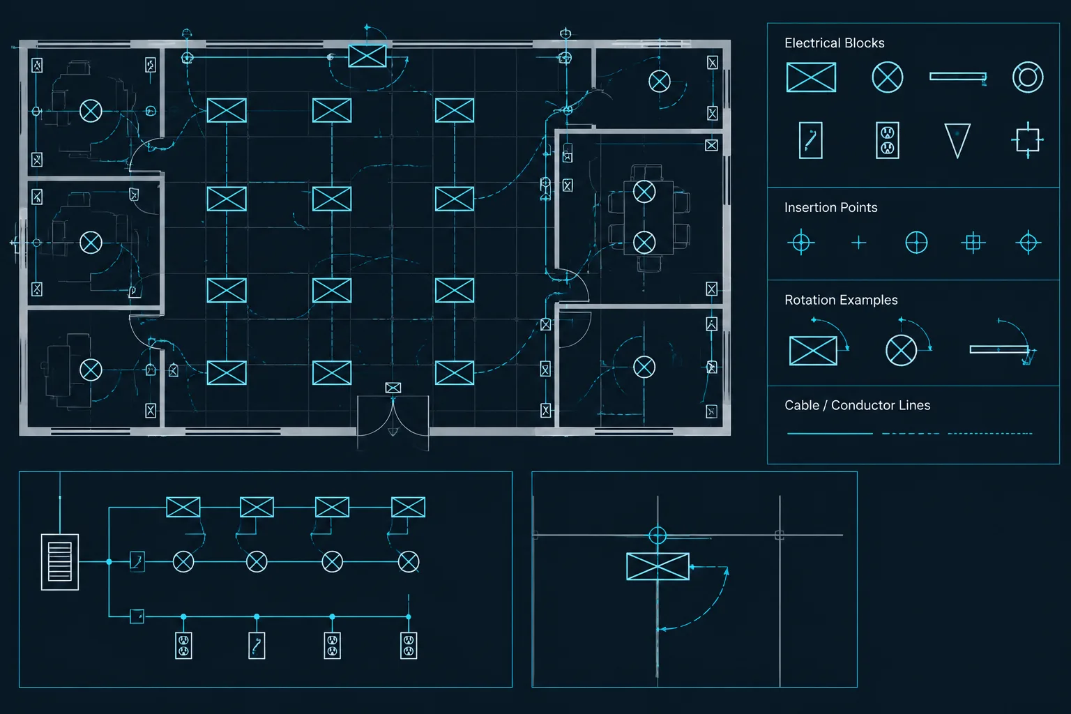
Reusable blocks can improve consistency for breakers, switches, transformers, generators, meters, transfer equipment, and distribution assemblies. Blocks should support the diagram rather than dictate an inflexible layout.
Useful block characteristics include a logical insertion point, predictable orientation, clean connection locations, and attributes that match the project’s data workflow. Before using a library block, verify its symbolism, units, layer behavior, text style, and attribute definitions. A familiar-looking symbol is not automatically appropriate for every project or drawing convention.
Separate graphic categories with layers
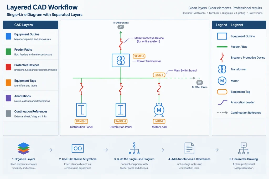
A layer structure can make editing and quality control more manageable. Projects may separate equipment outlines, feeder paths, symbols, tags, descriptive text, continuation references, revision graphics, and background information. The exact names should follow the applicable CAD standard.
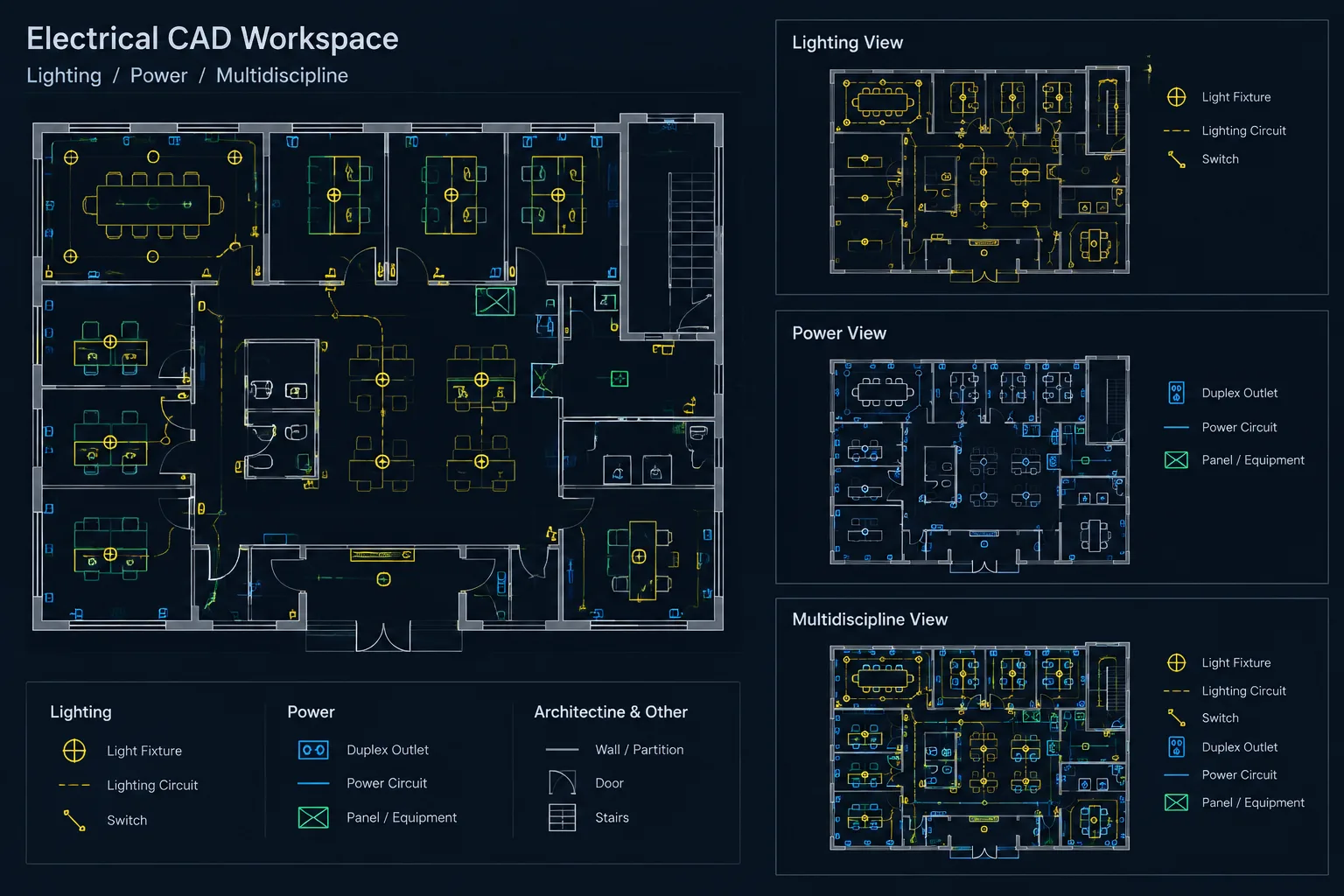
Layer separation helps reviewers isolate information and helps drafters avoid changing unrelated objects. It can also support alternate views, such as a simplified presentation diagram and a more detailed design diagram, without duplicating the underlying connectivity unnecessarily.
Plan sheet breaks and continuation references early
Large distribution systems may not fit clearly on one sheet. Do not wait until the diagram is complete before deciding where to divide it. Identify logical break points, such as a downstream distribution group or a distinct system, and reserve room for continuation labels.
Each continuation should identify where the power path resumes. The corresponding destination should provide a matching reference back to the originating location. Use the same equipment and feeder identifiers on both sides of the break.
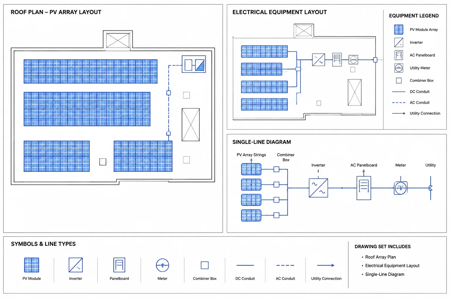
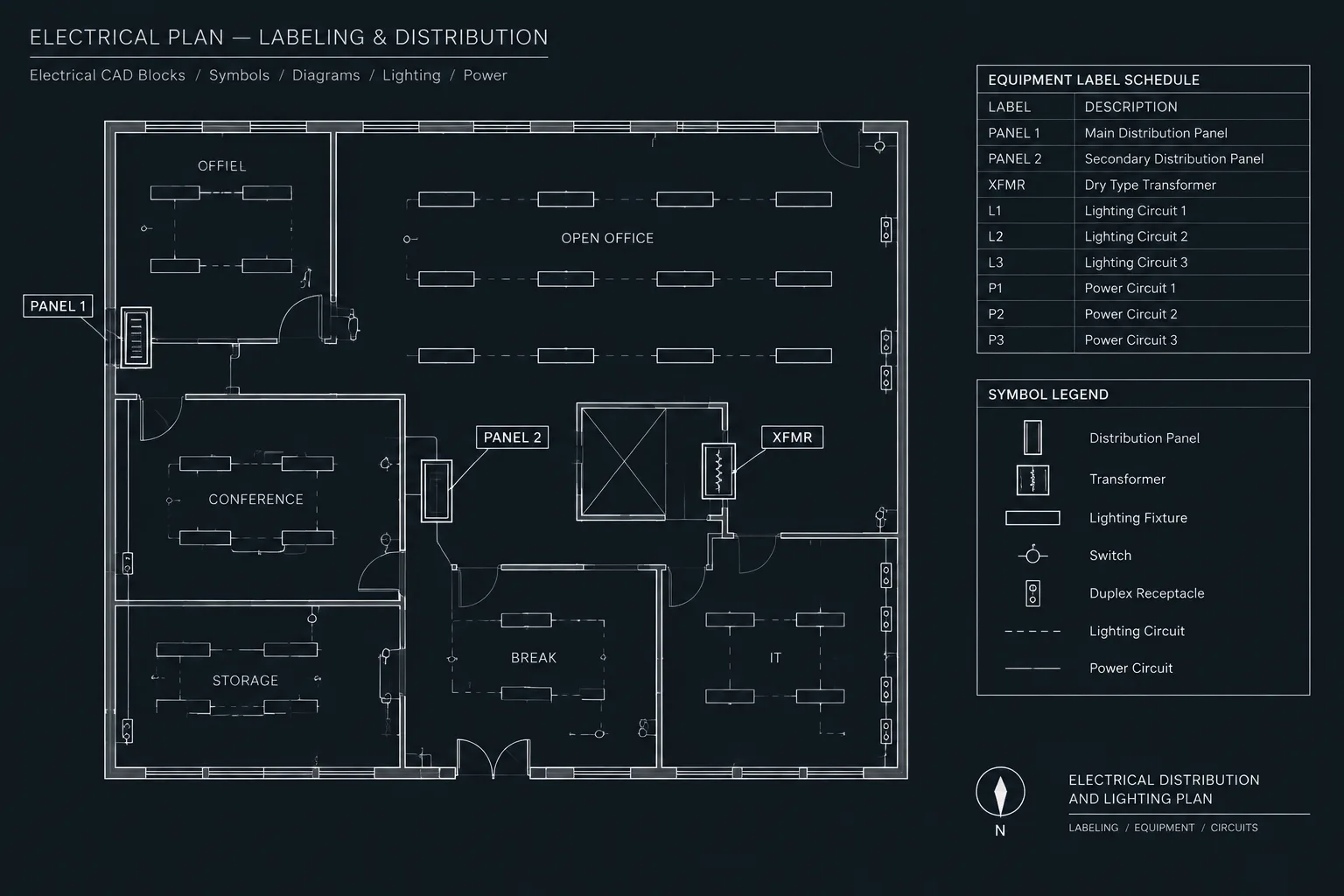
Coordinate the single-line with other documents
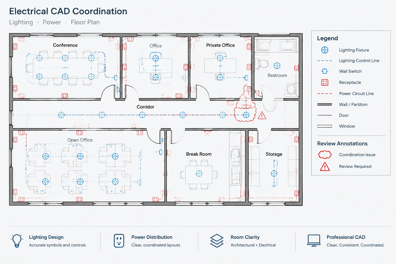
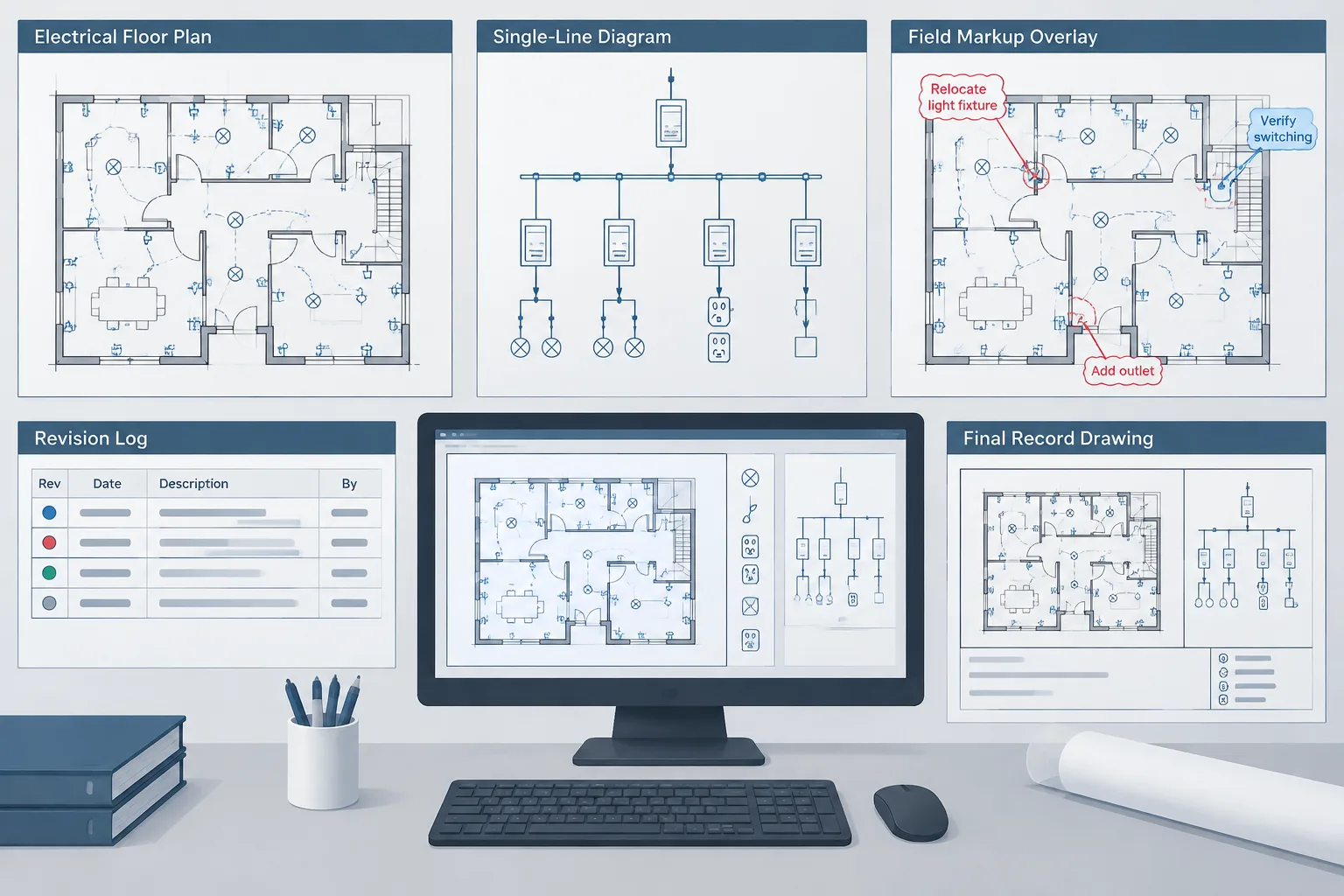
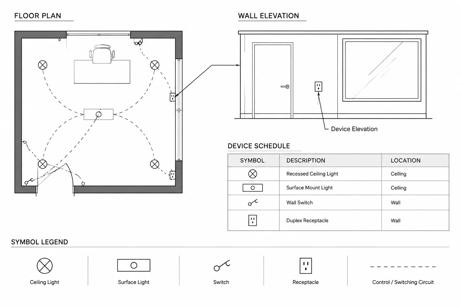
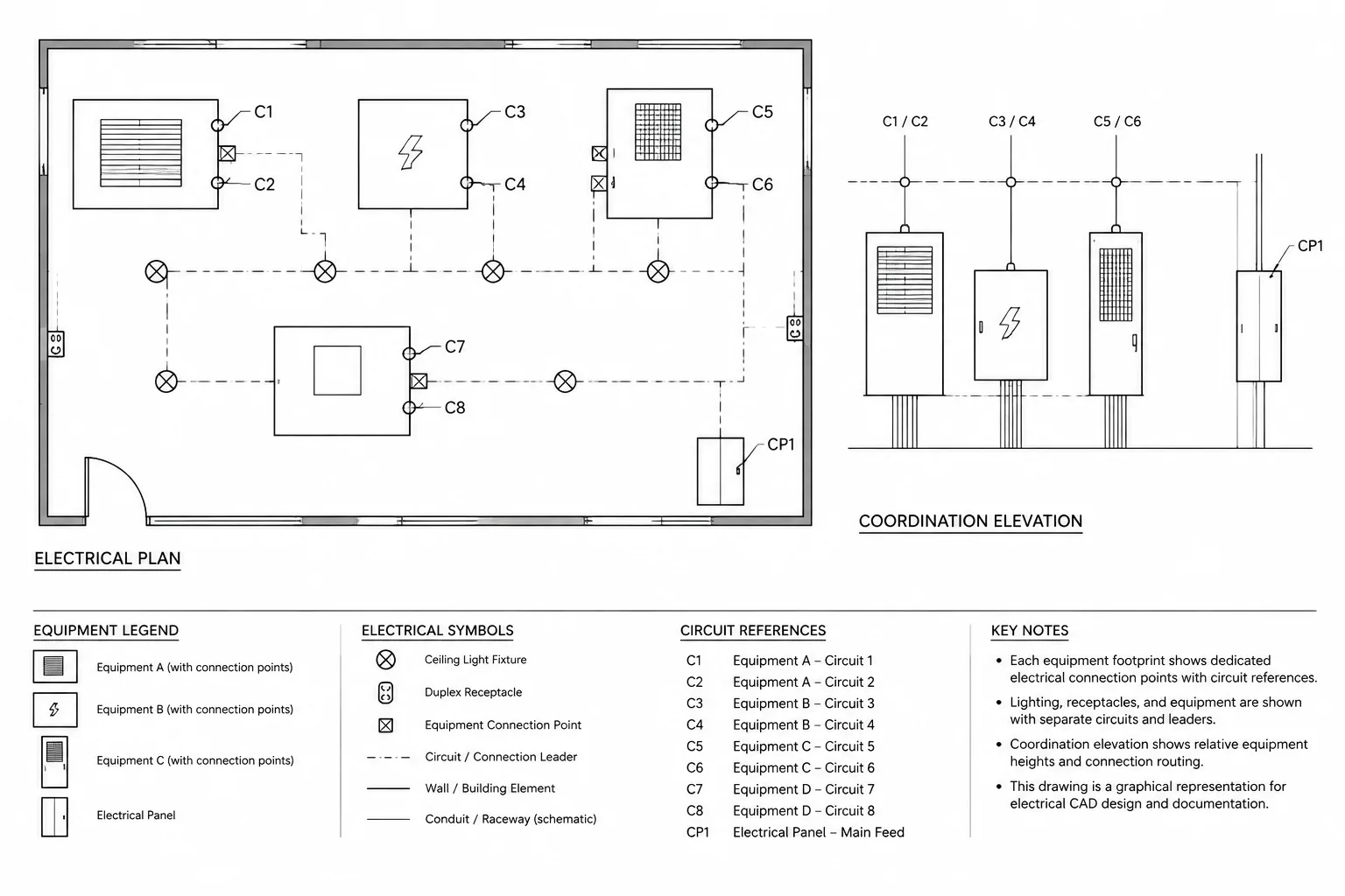
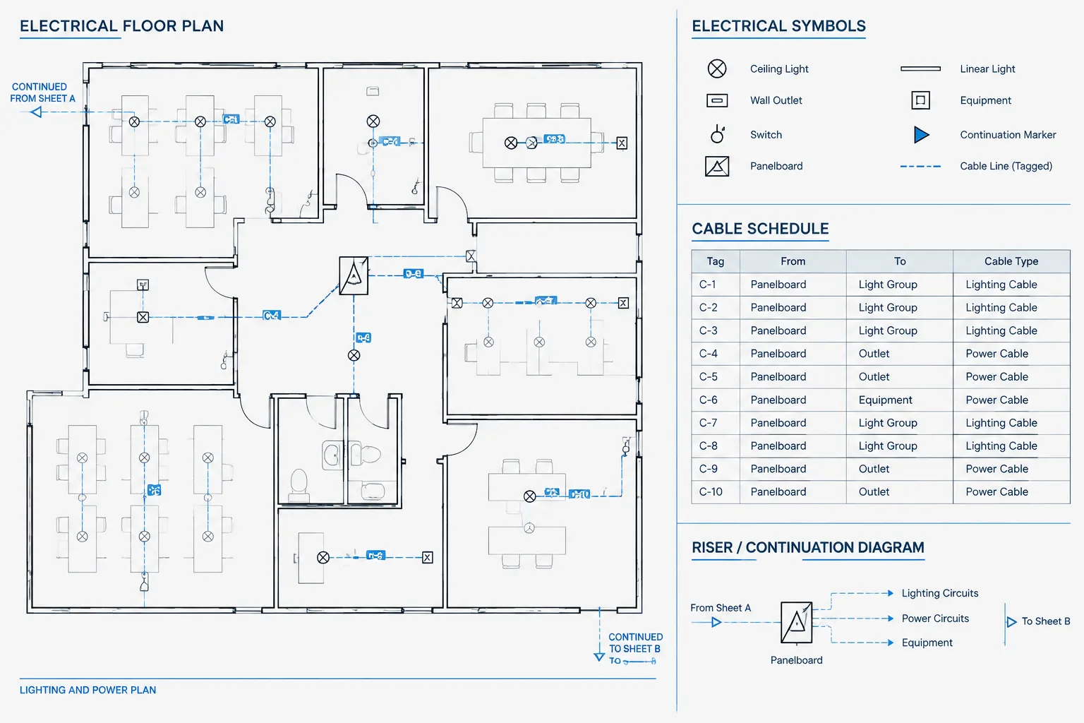
The single-line is part of a larger drawing and schedule system. Equipment tags should agree with floor plans, equipment layouts, panel schedules, feeder schedules, riser diagrams, and relevant details. If one document uses a different identifier for the same equipment, reviewers may interpret the entries as separate devices.
During coordination, compare both identity and relationship. Matching tags are not enough if the floor plan shows equipment in one system while the single-line connects it to another.
Perform a visual tracing review
A useful quality-control method is to trace each power path visually from source to final shown load. Perform this review without relying on design notes that are not visible on the sheet. If the path cannot be followed confidently, the layout needs clarification.
- Confirm that every feeder has two understandable endpoints or a continuation.
- Check that junctions and crossings cannot be confused.
- Verify that protective devices are associated with the intended feeders.
- Compare equipment tags with plans and schedules.
- Look for overlapping text, feeder lines, and symbol geometry.
- Review the plotted or exported output, not only the CAD model.
- Confirm that revised branches have not left obsolete lines or annotations behind.
Favor clarity over compactness
A compact diagram is not necessarily an efficient diagram. Saving sheet space by compressing branches can increase review time and raise the likelihood of misinterpretation. Where density becomes excessive, consider reorganizing the hierarchy, moving supporting data to schedules, creating an enlarged diagram area, or dividing the system across coordinated sheets.
The goal of single-line diagram layout in CAD is to make electrical relationships visible, traceable, and maintainable. When sources, buses, feeders, devices, and loads follow a deliberate graphic structure, the diagram becomes easier to coordinate throughout design revisions and easier for technical users to review.
A practical CAD layout review sequence
Layout quality is easier to evaluate when the drawing is reviewed in separate passes. Trying to check connectivity, annotation, graphics, and coordination at the same time can allow small conflicts to remain hidden.
Review the electrical relationships
- Trace each source through its associated distribution path.
- Confirm that each feeder reaches identifiable equipment, a defined load, or a documented continuation.
- Check that switching and protective device symbols remain associated with the intended path.
- Look for branches whose position could imply an incorrect upstream relationship.
Review the drawing geometry
- Check alignments among equipment serving similar diagram functions.
- Remove unnecessary bends, overlaps, and crowded crossings.
- Verify that connection points meet symbol geometry cleanly.
- Confirm that spacing communicates grouping without being mistaken for electrical data.
Review annotation and references
- Keep equipment tags visually attached to the correct symbols.
- Place feeder descriptions where their ownership is unambiguous.
- Check both ends of every continuation reference.
- Compare identifiers with plans, schedules, risers, and equipment layouts.
Review the deliverable
Inspect the plotted or exported document rather than relying only on the CAD workspace. Layer colors, display settings, and zoom level can conceal crowded text or weak line separation. The issued view should remain understandable without requiring access to the authoring file.
Maintain the diagram through revisions
A clear initial layout can deteriorate when later changes are added wherever space happens to be available. Treat each revision as a change to the distribution hierarchy, not merely as new linework. Recheck adjacent branches, tag placement, continuation references, and supporting schedules whenever equipment or connectivity changes.
Unused symbols, abandoned feeder segments, duplicate tags, and outdated notes should be resolved as part of the same revision. This keeps the single-line diagram useful as a coordinated project document rather than a collection of accumulated edits.
Frequently asked questions
Does spacing on a single-line diagram represent electrical capacity?
No. Diagram spacing is primarily a graphic organization tool. Ratings, capacities, conductor information, and other design data must be communicated through verified labels, schedules, notes, and project documents.
Should every single-line diagram use the same reading direction?
Not necessarily. The most appropriate direction depends on the system hierarchy and sheet arrangement. The important drafting goal is to maintain a predictable direction within related diagrams and avoid unexplained reversals.
When should a large diagram be divided across sheets?
A sheet break may be appropriate when density prevents clear tracing, annotation, or comparison. Break the diagram at a logical system boundary and provide matching continuation references so the connection can be followed in both directions.
Can standard CAD blocks be inserted without review?
No. Library blocks should be checked against the project’s symbol conventions, units, layers, text behavior, attributes, orientation, and connection points before use.
How can a drafter tell whether a layout is too crowded?
The layout is likely too crowded when feeder ownership is uncertain, crossings resemble junctions, tags compete with linework, or the power path becomes difficult to trace in the issued output. Reorganization is usually more effective than compressing additional information into the same area.
What should be checked after moving equipment on the diagram?
Recheck feeder endpoints, device associations, equipment tags, text leaders, continuation references, and coordination with other drawings and schedules. Moving a symbol can affect more than its visible position.
Leave a Reply
You must be logged in to post a comment.