
Electrical CAD plot styles connect drawing properties with the appearance of issued sheets. When that connection is not understood, otherwise accurate plans and diagrams can publish with weak contrast, inconsistent linework, or distracting backgrounds.
This guide explains how CTB and STB workflows affect electrical documentation, how to inspect incoming files, and how to coordinate plot styles with layers, blocks, xrefs, page setups, and quality-control reviews. The goal is not to prescribe a universal appearance, but to help teams produce repeatable output that reflects the intended drawing hierarchy.
Electrical CAD drawings often look correct on screen but lose their hierarchy when plotted. Circuiting may compete with architectural walls, equipment outlines may disappear into the background, and notes may become difficult to distinguish from secondary information. In many CAD workflows, these problems are controlled partly through plot styles.
A plot style translates drawing properties into printed or PDF appearance. Depending on the drawing configuration, that translation may be based on object color or on a named style assigned to objects and layers. Understanding this relationship is essential when maintaining electrical plans, one-line diagrams, schedules, and details created by different teams.
What a plot style controls
A plot style can influence how an object is represented in output without changing its model-space geometry. Common plotted properties include lineweight, screening, grayscale behavior, and whether a displayed color is converted to another plotted color. The available controls depend on the CAD platform and plotting configuration.
Plot styles work alongside layers, object properties, linetypes, drawing scale, viewport settings, and page setup. They are not a replacement for a disciplined layer structure. Instead, they form one part of the system that turns model information into a readable sheet.
For an electrical plan, that system might make new electrical work visually prominent, show the architectural background more lightly, retain a recognizable dashed linetype for overhead routing, and keep annotations legible. The exact appearance should follow the project’s documented CAD and publishing requirements.
CTB and STB workflows
Two widely encountered plot-style methods are color-dependent plot styles and named plot styles. Their associated files are commonly identified as CTB and STB files.
| Workflow | How plotted appearance is assigned | Typical coordination concern |
|---|---|---|
| CTB | The object’s indexed color points to a corresponding plot-style definition. | Changing an object color can unintentionally change its plotted lineweight or screening. |
| STB | A named plot style is assigned to a layer or object independently of its display color. | Objects may plot unexpectedly if their named style is missing, overridden, or misunderstood. |
Neither method is automatically better for every electrical project. The important requirement is consistency. A drawing configured for one system should be published with the correct supporting plot-style file, page setup, and layer standards.
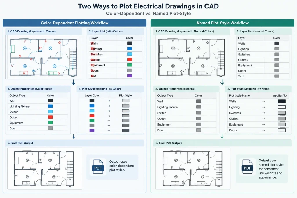
Color-dependent plotting
In a CTB workflow, indexed drawing colors carry publishing meaning. A project team may use particular colors for heavier, lighter, screened, or otherwise differentiated output. This makes color selection more than a visual preference.
The method can be efficient when an established office template already coordinates colors, layers, and plotted lineweights. It can also cause confusion when blocks arrive from another source. A symbol that appears normal on screen may use a color that maps to an inappropriate lineweight in the receiving project.
True-color or nonstandard color usage also requires careful testing because it may not behave like the indexed colors anticipated by the project’s plot configuration.
Named plotting
In an STB workflow, descriptive plot-style names can express publishing intent independently of display color. A team might distinguish prominent, standard, secondary, screened, or nonprinting information through named styles, provided those names are clearly documented.
This separation can make layer colors easier to use for on-screen organization. However, named styles still require governance. If users assign different styles directly to individual objects, the drawing can accumulate overrides that are difficult to audit.
How plot styles support electrical drawing hierarchy
Good electrical documentation uses graphic hierarchy to communicate meaning. Plot styles should help readers distinguish information categories rather than merely make a sheet look polished.
- Primary electrical scope: Equipment, devices, feeders, and essential diagram connections should be easy to find.
- Secondary electrical information: Circuit lines, control relationships, and supporting notes should remain readable without overwhelming the sheet.
- Reference backgrounds: Architectural, structural, or mechanical context should support location coordination while remaining visually subordinate where appropriate.
- Annotations: Tags, keynote markers, panel identifiers, and cross-references need enough contrast to survive plotting and reduction.
- Nonprinting construction aids: Viewport guides, working boundaries, and temporary coordination graphics should be placed on layers intentionally configured not to publish.
These categories do not require universal lineweights or colors. Their implementation should be based on the project template, drawing type, output size, and office standards.
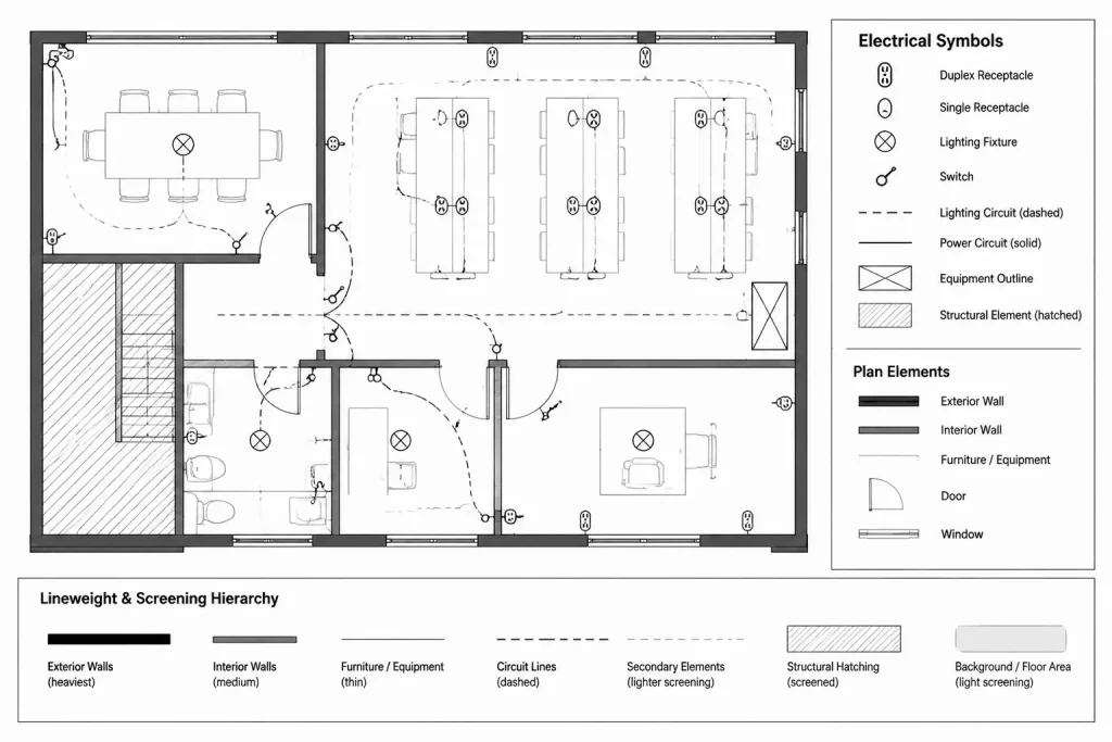
A practical setup workflow
1. Identify the drawing’s plot-style mode
Before editing colors or lineweights, determine whether the drawing uses color-dependent or named plot styles. Do not assume that a file follows the same method as another project simply because the layers have similar names.
2. Confirm the required support file
Verify that the correct plot-style file is available and selected. A substitute file with a similar name may contain completely different mappings. If an external consultant supplied the drawing, request the publishing resources and instructions needed to reproduce its intended output.
3. Review layer properties before object overrides
Electrical drawings are easier to maintain when most graphic behavior is controlled by layer. Inspect layer color, lineweight, linetype, transparency, and plot status before changing individual symbols or lines.
Object-level overrides may be justified for limited cases, but widespread overrides can make the drawing unpredictable. Blocks deserve special attention because their internal geometry may use fixed properties rather than inheriting properties from the insertion layer.
4. Test representative content
Create or use a test sheet containing typical electrical symbols, text, leaders, circuit lines, equipment outlines, hatches, xref backgrounds, and diagram connections. A useful test includes both dense and open areas of a drawing.
Check the actual PDF or printed output rather than relying only on the on-screen preview. Review the sheet at normal reading size and at reduced viewing sizes commonly used during coordination.
5. Standardize page setups
Plot-style selection should be coordinated with the sheet size, output device or PDF configuration, orientation, plot area, scale, and other page-setup properties. Saved and consistently applied page setups reduce the chance that individual sheets are published differently.

6. Record the workflow
Document whether the project uses CTB or STB, identify the required file, and explain any project-specific layer or color conventions. Include this information in the CAD execution documentation or issue checklist rather than relying on team memory.
Working with imported blocks and consultant drawings
Downloaded CAD blocks and external drawings should be treated as source material, not as automatically compliant project content. Before placing an electrical block into a production file, inspect its layers, internal colors, lineweights, linetypes, and plot-style assignments.
A practical cleanup process is to work in a controlled staging file. Remove unnecessary layer dependencies, place geometry on approved layers where appropriate, and set properties to inherit from the intended layer when that matches the office block standard. Preserve distinctions that carry real drawing meaning, such as separate annotation, hidden geometry, or equipment outlines.
Xrefs require a different approach. Avoid making uncoordinated changes directly to another discipline’s background merely to improve plotting. Use the project’s layer-override and publishing workflow so that the source drawing remains traceable and can be reloaded without losing the intended electrical presentation.
Common plot-style problems
| Symptom | Likely area to investigate |
|---|---|
| Everything plots with similar visual weight | Incorrect plot-style file, ineffective mappings, or objects using unexpected properties |
| A block plots much heavier than nearby symbols | Fixed colors or lineweights inside the block definition |
| An xref background dominates the electrical work | Unmanaged xref layer properties, screening, or viewport overrides |
| Some colored objects remain colored in a monochrome issue | True-color objects, embedded raster content, or incomplete plot conversion settings |
| One sheet differs from the rest of the set | Different page setup, plot-style selection, viewport properties, or publishing configuration |
| Working guides appear in the issued PDF | Incorrect layer plot status or geometry placed on a publishable layer |
Plot-style quality-control checklist
- Confirm the drawing uses the intended CTB or STB system.
- Verify the correct plot-style file is available and selected.
- Check representative electrical layers and xref layers.
- Inspect block contents for fixed property overrides.
- Review screened information for readability rather than assuming lighter is always better.
- Confirm dashed and center linetypes remain recognizable in output.
- Check text, leaders, tags, and schedule borders at final sheet scale.
- Compare page setups across every sheet in the issue set.
- Open the published PDF and inspect both dense plans and diagram sheets.
- Archive the required publishing resources with the project according to the organization’s document-control procedure.
Build the publishing system around intent
Electrical CAD plot styles are most reliable when they express a deliberate hierarchy shared by layers, blocks, xrefs, and page setups. CTB and STB are simply different mechanisms for assigning that output behavior. A consistent method, documented support files, controlled object properties, and PDF review are more important than choosing one system based on preference alone.
When the plot-style workflow is treated as part of electrical documentation rather than a final printing adjustment, drawings are easier to exchange, review, revise, and reproduce.
Choosing a workflow based on project control
The practical choice between CTB and STB is usually determined by the established project environment. Existing templates, consultant requirements, archived drawings, layer conventions, and publishing procedures all influence which method can be maintained reliably.
A CTB workflow is easier to control when users understand that indexed color carries plotting meaning. An STB workflow is easier to control when named styles are documented and assigned consistently. Either method becomes difficult to manage when users rely heavily on object-level overrides or receive files without the supporting plot configuration.
Avoid changing methods only to solve a local plotting problem
Converting or reorganizing a drawing solely because one block or xref plots incorrectly can create broader coordination issues. First investigate the affected layer, object properties, block definition, viewport overrides, page setup, and selected plot-style file. A localized property conflict is often better handled through controlled cleanup than through a project-wide workflow change.
If a conversion is required by the project team, retain an unchanged source file and test the result in a separate working copy. Review representative plans, diagrams, details, schedules, text, hatches, and external references before accepting the converted file for production use.
Plot-style governance for shared electrical files
A reliable publishing workflow should make the intended output reproducible by someone other than the drawing author. The project record should identify the plot-style method, required support file, approved page setup, relevant layer conventions, and any intentional exceptions.
- For internal blocks: Define whether nested geometry should inherit layer properties or retain controlled distinctions.
- For consultant files: Keep the received source traceable and document any display or viewport overrides used for electrical sheets.
- For sheet sets: Apply coordinated page setups instead of configuring each layout independently.
- For archived deliverables: Preserve the publishing resources needed to reproduce the issued appearance.
- For quality control: Review the generated PDF, not only model space or plot preview.
What a successful plot-style review should confirm
The final review should answer a communication question: can readers quickly distinguish electrical scope, supporting information, annotations, backgrounds, and nonprinting construction aids? A technically valid file can still be difficult to read if these categories compete visually.
Plot styles should therefore be evaluated together with lineweights, linetypes, layer states, viewport settings, and sheet scale. The most dependable workflow is the one that preserves drawing intent across editing, exchange, publishing, and later revision.
Frequently asked questions
What is the main difference between CTB and STB plotting?
CTB plotting maps indexed object colors to plot-style definitions. STB plotting assigns named plot styles to layers or objects independently of display color. Both methods still depend on coordinated layers, page setups, and object properties.
Why does an electrical block plot differently after it is inserted?
The block may contain fixed colors, lineweights, linetypes, or plot-style assignments that do not inherit from the insertion layer. Inspect the block definition in a controlled staging file before changing the production drawing.
Why does an xref overpower the electrical plan?
The referenced layers may retain properties that give the background too much visual emphasis. Review the project’s approved xref layer and viewport-override workflow rather than editing another discipline’s source without coordination.
Can a missing plot-style file change PDF output?
Yes. If the required file is unavailable or a different file is selected, mapped lineweights, screening, grayscale behavior, and plotted colors may not match the intended appearance.
Should display colors match the final plotted colors?
Not necessarily. In a CTB workflow, display color may serve as a publishing control. In an STB workflow, display color can be separated from named plotting behavior. The project documentation should make the relationship clear.
Is plot preview enough for quality control?
No. Preview is useful, but the published PDF should also be inspected for hierarchy, text clarity, linetype recognition, background treatment, and consistency across sheets.
Should imported drawings be converted from CTB to STB or from STB to CTB?
Only when the project workflow requires conversion and the effects can be tested. Keep the original source, verify property mappings, and review representative content before using the converted drawing for production.












Leave a Reply
You must be logged in to post a comment.