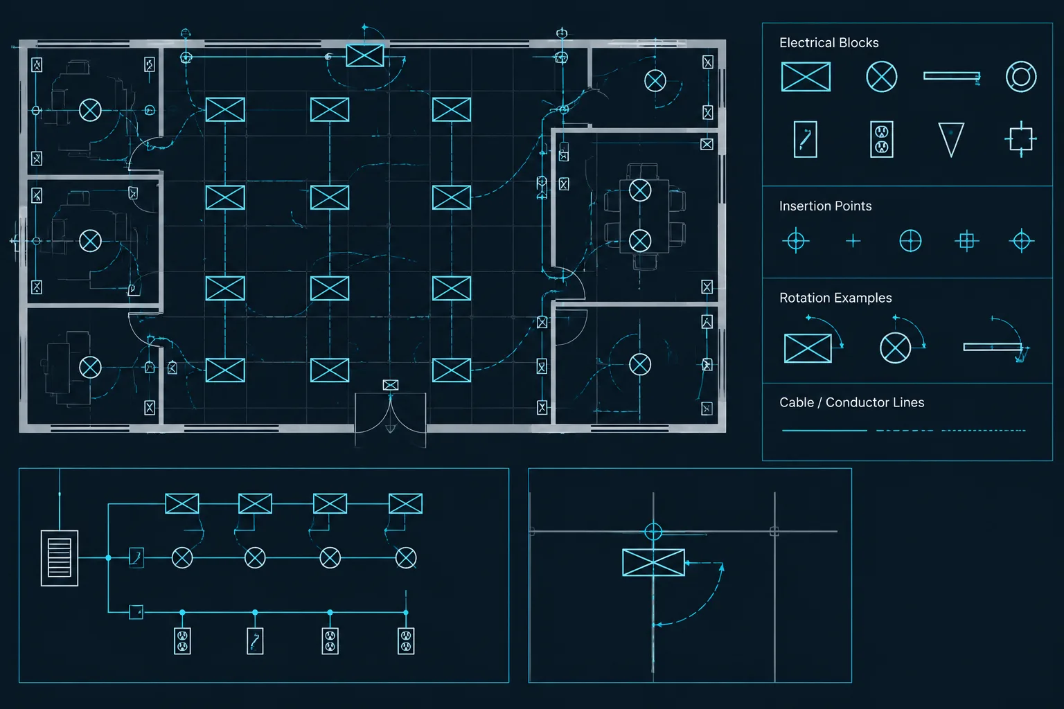
Reliable electrical blocks depend on more than recognizable geometry. The point attached to the cursor, the block’s default direction, and the behavior of labels during rotation or mirroring all influence drafting speed and drawing consistency.
This workflow focuses on evaluating those behaviors before a block enters a shared library. It applies to plan symbols, schematic components, equipment footprints, and annotations while leaving project-specific design decisions to the responsible design team and office CAD standard.
An electrical symbol can look correct in a block library yet become frustrating when placed in a real drawing. It may attach to the cursor from an unexpected corner, rotate around the wrong location, flip its text when mirrored, or sit slightly away from the wall or circuit line it is meant to represent.
These problems usually come from the block definition rather than the visible symbol geometry. A reliable block needs a deliberate insertion point, a predictable orientation, and behavior suited to its drawing context. Establishing those characteristics makes symbols faster to place and easier to replace, schedule, and review.
This guide explains how to evaluate and prepare electrical CAD blocks for plans, diagrams, and equipment layouts. It focuses on drafting behavior rather than project-specific design approval. Symbols, orientations, and installation conditions must still be checked against the project requirements and the office CAD standard.
What an insertion point controls
The insertion point, sometimes called the block base point, is the location used to pick up and place a block. It also acts as the center for many block operations, including rotation and scale changes.
A good insertion point corresponds to a meaningful drafting location. Depending on the symbol, this might be:
- The center of a ceiling-mounted device.
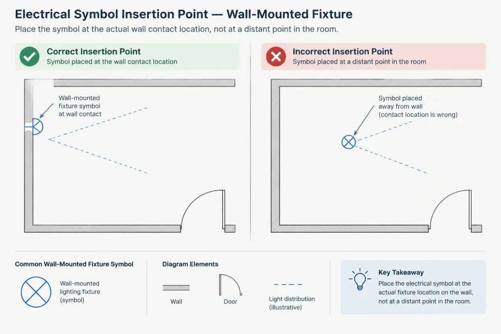
- The wall contact point of a receptacle or switch symbol.
- The connection node of a schematic component.
- The centerline intersection of equipment shown in plan.
- A defined equipment corner used for layout coordination.
- The origin of a diagram symbol that must align with conductors.
An arbitrary insertion point may not affect the appearance of a block at first, but it increases placement effort. Drafters must move, rotate, or visually adjust every instance instead of snapping it directly to the intended location.
Choose the insertion point from the placement task
The most useful base point depends on how the block is used. Avoid applying one base-point rule to every symbol in a library.
| Block category | Useful insertion-point concept | Drafting benefit |
|---|---|---|
| Wall-mounted device | Point where the symbol meets the wall or device line | Supports direct snapping to the architectural background |
| Ceiling device | Geometric or functional center | Helps align devices with ceiling grids and layout guides |
| Schematic component | Primary terminal, connection node, or logical center | Keeps wires and connection points aligned |
| Lighting fixture | Fixture center or another documented layout origin | Supports arrays, alignment, and coordinated placement |
| Equipment footprint | Centerline intersection or a documented reference corner | Provides a repeatable origin for equipment layouts |
| Tag or callout | Leader attachment point or center of the tag frame | Makes annotation placement more predictable |
The chosen point should remain stable if minor graphics are revised. For example, a receptacle block may gain an attribute or status marker without changing the wall contact point. Moving the base point during that revision can cause unexpected shifts when existing instances are redefined.
Set a clear default orientation
Every reusable block should have an understood zero-rotation orientation. The specific direction is less important than consistency and documentation. A mixed library in which similar symbols face different directions at zero rotation forces users to rely on trial and error.
For plan symbols, select an orientation that supports the most common placement condition. For diagram symbols, orient terminals and connection paths so they align naturally with the office’s typical diagram flow. Equipment blocks should follow a consistent plan-view convention for fronts, doors, access sides, and connection sides.
When reviewing orientation, consider both the symbol and its data. A block may rotate correctly while its tag becomes upside down or collides with nearby geometry. Treat graphic orientation and annotation orientation as related but separate behaviors.
Use rotation instead of maintaining unnecessary duplicates
Separate left-, right-, up-, and down-facing blocks can make a library difficult to maintain. If a symbol can be rotated without changing its meaning or damaging its annotation, one well-built definition is generally easier to manage.
Separate blocks may still be appropriate when orientation represents a genuinely different device, connection arrangement, or documentation condition. The goal is not to eliminate every variation, but to avoid creating duplicates solely to compensate for a poorly selected insertion point.
Understand the risks of mirroring
Mirroring can be convenient when laying out repeated rooms or opposite wall conditions, but not every electrical block should be mirrored. The operation can reverse text, alter the apparent handedness of equipment, or create a symbol variation that has a different meaning.
Before allowing a mirrored block to remain in a drawing, check:
- Whether attributes and labels remain readable.
- Whether the symbol is intended to be symmetrical.
- Whether equipment doors, hinges, controls, or connection sides now appear incorrectly.
- Whether schematic terminals retain the intended identification and sequence.
- Whether leaders, wipeouts, masks, and status graphics still display properly.
- Whether the mirrored result matches the project legend.
A system setting that keeps text readable can reduce reversed lettering, but it does not confirm that the complete block remains technically correct. Graphic handedness and equipment configuration still require review.
Rotation and mirroring are not interchangeable
Rotating a block preserves the relationship between its left and right sides. Mirroring reverses that relationship. For a simple circular device symbol, the visible difference may be negligible. For an equipment footprint with a defined front or a diagram component with identified terminals, the distinction can be important.
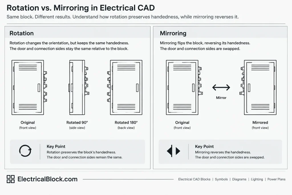
If a block frequently needs an opposite-handed form, decide whether that form should be a controlled block state, a separate verified definition, or a mirrored instance. Make the decision intentionally rather than leaving it to individual drafting preference.
Keep attributes readable and stable
Attributes add device identifiers, circuit references, mounting notes, or other project data to a block. Their placement should be tested through the expected rotation range.
For each attributed block, review whether the text should:
- Rotate with the symbol.
- Remain horizontal on the plotted sheet.
- Move to another position for specific orientations.
- Stay centered or justified relative to the insertion point.
- Remain visible in every intended block state.
There is no universal answer. Diagram terminal labels may need to follow a component, while plan tags are often easier to read when kept upright. Whichever behavior is selected should be consistent among blocks serving the same purpose.
Also test longer sample values rather than checking only short default text. A block that works with a single-character placeholder may produce overlaps when populated with realistic project identifiers.
Place connection nodes precisely
Schematic and single-line symbols require special attention because conductors must meet their connection points cleanly. A tiny offset can create visible gaps, overshoots, or false intersections in plotted output.
Build connection nodes on the drawing’s intended drafting grid and verify them using object snaps rather than visual alignment alone. If a component has several terminals, their spacing should be internally consistent and compatible with the diagram workflow used by the project team.
Do not add decorative linework that obscures the true connection location. A user should be able to identify where a conductor terminates without exploding the block or inspecting hidden construction geometry.
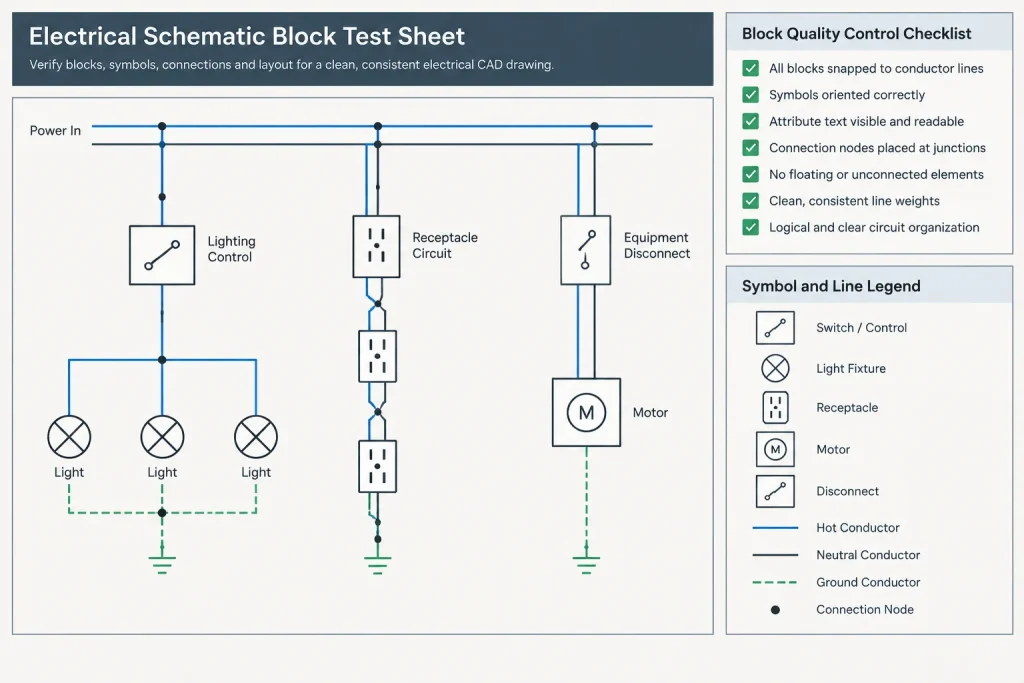
Test blocks in a temporary drawing
Library maintenance should include a placement test outside the source file. A clean test drawing exposes dependencies and behavior that may be hidden in the block-development file.
A practical test sequence includes:
- Insert the block at its intended drawing scale and confirm that it attaches to the cursor at the expected point.
- Snap it to representative walls, grid intersections, conductors, or equipment reference lines.
- Rotate it through the orientations commonly used in drawings.
- Mirror it only if mirroring is part of the intended workflow.
- Edit every attribute using realistic sample values.
- Check layer assignment, color, linetype, and lineweight behavior.
- Plot or preview the symbol at the sheet conditions where it will be used.
- Redefine the block with a revised copy and confirm that existing instances do not shift unexpectedly.
Testing should also include nearby annotation and adjacent symbols. A block may be clear in isolation but difficult to use in a dense electrical room, ceiling plan, or schematic.
Avoid distant and accidental base points
A common library defect is a base point located far from the visible geometry. This may result from creating the block with the wrong origin, retaining stray objects, or copying geometry from another file without resetting the reference point.
Warning signs include a block that disappears from view during insertion, rotates in a large circle, creates unexpectedly large drawing extents, or requires zooming out to locate. Inspect both the block definition and its surrounding source geometry. Remove stray entities, verify the intended origin, and retest the definition in a clean file.
Document the block convention
A short library note can prevent inconsistent edits later. Record the intended insertion-point concept, default orientation, allowed scaling behavior, attribute orientation, and whether mirroring is acceptable.
For equipment blocks, the note can also identify which graphic edge represents the front or service side. For diagram symbols, it can state which point is treated as the primary connection. These notes describe drafting behavior; they do not replace project design criteria or manufacturer information.
Final review checklist
- The insertion point represents a meaningful placement or connection location.
- The block has a consistent and recognizable zero-rotation orientation.
- Rotation occurs around the expected point.
- Attributes remain readable and do not collide with geometry.
- Mirroring is either verified for the block or clearly discouraged.
- Connection nodes snap precisely to diagram lines.
- Minor block revisions will not unnecessarily move existing instances.
- No stray geometry creates distant extents or unexpected cursor behavior.
- The block has been tested in a clean drawing and in a representative sheet view.
Thoughtful electrical CAD block insertion points reduce repetitive adjustment and improve drawing consistency. When rotation, mirroring, connections, and attributes are tested as part of the block definition, library symbols become dependable drafting tools rather than isolated pieces of geometry.
Manage corrections at the right level
When a placement problem appears, determine whether it belongs to the block definition or only to a particular block reference. Correcting the definition is appropriate when every new instance attaches from the wrong location, rotates unpredictably, or carries the same annotation defect. A reference-level adjustment may be more appropriate when the issue is unique to one drawing condition.
This distinction matters in shared libraries. Editing individual references can hide a defective definition, while redefining a block to solve an isolated layout problem can disrupt otherwise correct instances. Review several placements before deciding where the correction belongs.
Separate graphic quality from placement quality
A symbol can be visually accurate but operationally inefficient. Library review should therefore consider both its appearance and its behavior. Graphic review addresses linework, legibility, and recognizable form. Placement review addresses the base point, orientation, snapping, attributes, and response to permitted transformations.
Keeping these checks separate makes review comments clearer. Instead of noting that a block “does not work,” a reviewer can identify whether the defect concerns geometry, annotation, connection alignment, or insertion behavior.
Use consistent acceptance criteria
A shared library benefits from a repeatable approval process. Reviewers should confirm that similar block categories follow the same placement logic, that any exceptions are documented, and that corrected definitions have been tested outside their development files.
- Plan symbols: Confirm that the base point supports alignment with walls, grids, or layout centers.
- Diagram symbols: Confirm that conductors meet identifiable connection nodes without visual adjustment.
- Equipment footprints: Confirm that the documented origin and orientation communicate the intended reference side.
- Attributed blocks: Confirm that realistic text remains readable in approved orientations.
- Mirrored references: Confirm that the result preserves meaning rather than merely preserving readable text.
These checks support drafting consistency, but they do not verify equipment selection, installation conditions, or compliance with project requirements.
Frequently asked questions
Should every electrical CAD block use its geometric center as the insertion point?
No. The most useful point is the location that supports the intended placement task. A wall device may need a wall contact point, while a schematic component may need a terminal or logical connection node.
Why does a block move in a large arc when rotated?
The base point may be distant from the visible geometry. Stray entities or an unintended origin can also expand the definition’s extents and make insertion or rotation difficult to control.
Is rotating a block the same as mirroring it?
No. Rotation changes direction while preserving left-to-right relationships. Mirroring reverses those relationships and may alter handed equipment, terminal arrangements, leaders, or annotation behavior.
When should opposite-facing symbols use separate definitions?
Separate definitions may be justified when orientation represents a different device, connection arrangement, or documented condition. If direction changes only for placement and the annotation remains reliable, a single rotatable definition may be easier to maintain.
How can a drafter tell whether the block definition is defective?
Insert the block into a clean test drawing and compare several references. If the same attachment, rotation, snapping, or attribute problem occurs consistently, the definition likely requires review.
Can readable mirrored text prove that a mirrored block is correct?
No. Readable text addresses only annotation display. The symbol’s handedness, connection sequence, equipment orientation, and relationship to the project legend still need verification.












Leave a Reply
You must be logged in to post a comment.