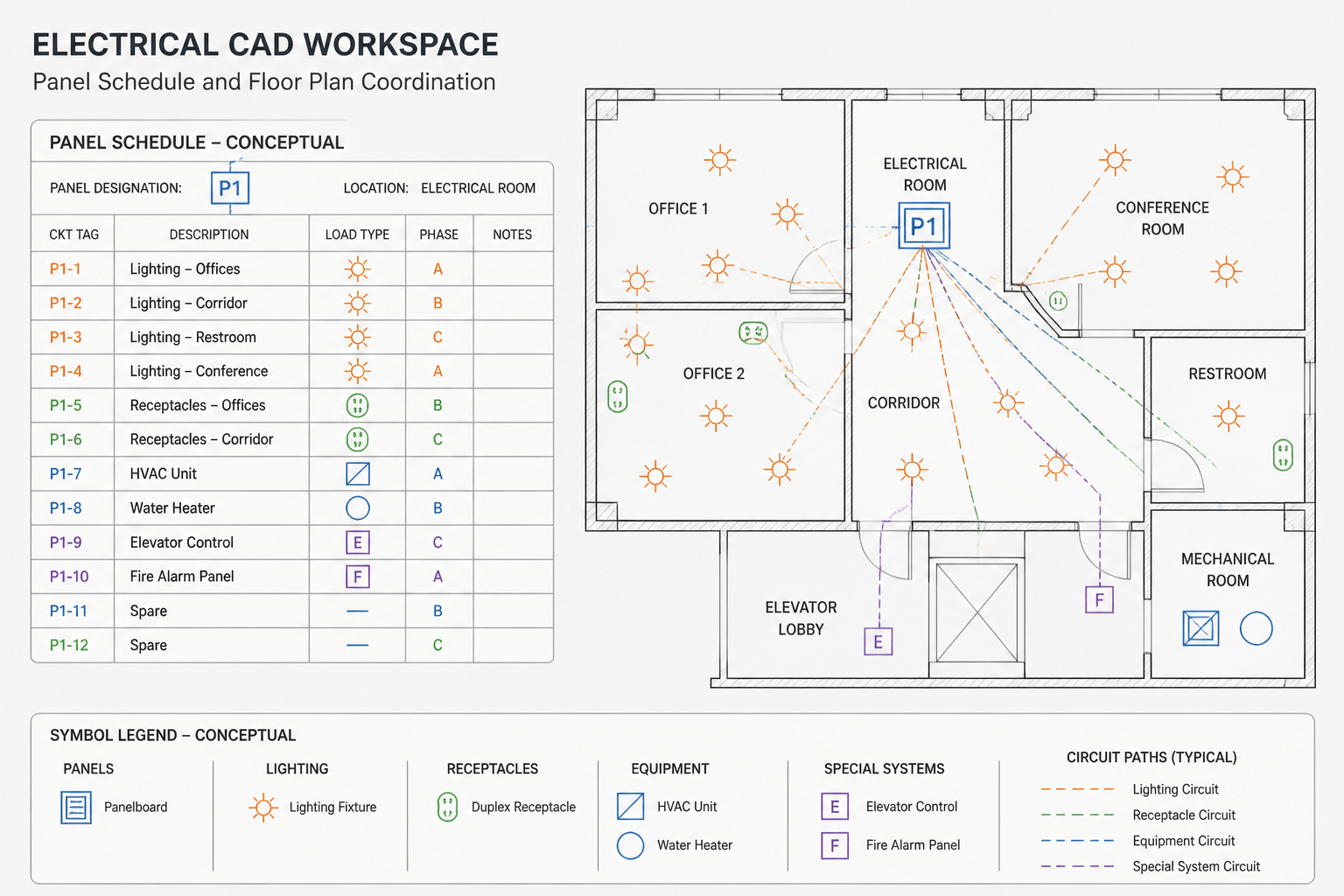
An electrical panel schedule is the information bridge between a distribution panel and the circuits shown elsewhere in an electrical drawing set. It organizes circuit identifiers, descriptions, connected loads, protective-device information, and other design notes in a compact tabular format. The floor plan shows where devices and equipment are located; the panel schedule explains how those items are grouped and served from a panel.
For CAD users, understanding that relationship is more useful than memorizing a particular schedule layout. Different offices, projects, and software templates arrange the fields differently. The underlying task remains the same: trace the relationship between the panel, its circuit references, the connected devices, and the drawing notes without treating a schedule as a substitute for the complete electrical design.
What an electrical panel schedule communicates
A panel schedule commonly identifies the panel name or designation and provides a structured list of outgoing circuits. Depending on the project, it may also include descriptions of loads, circuit grouping, phase or pole information, conductor references, protective-device details, load calculations, spare positions, and general notes.
These fields should be read as related information rather than isolated labels. A circuit description such as lighting, receptacles, mechanical equipment, or a dedicated appliance points to a physical or functional group elsewhere in the drawings. The circuit identifier provides the connection between that description and the corresponding plan symbol, equipment connection, or detail.
| Schedule element | What to look for | Related drawing information |
|---|---|---|
| Panel designation | The name used to identify the distribution equipment | Panel symbol, equipment layout, riser, or single-line diagram |
| Circuit identifier | The reference assigned to an outgoing circuit | Home-run notation, circuit tag, or connected load on the plan |
| Load description | A plain-language description of the served equipment or area | Lighting fixture, receptacle, motor, appliance, or mechanical equipment symbol |
| Device or protection field | Information describing the associated circuit device or arrangement | Notes, diagram annotations, or equipment schedules |
| Remarks | Special coordination or design information | General notes, detail references, or equipment connection notes |
How the schedule relates to the electrical plan
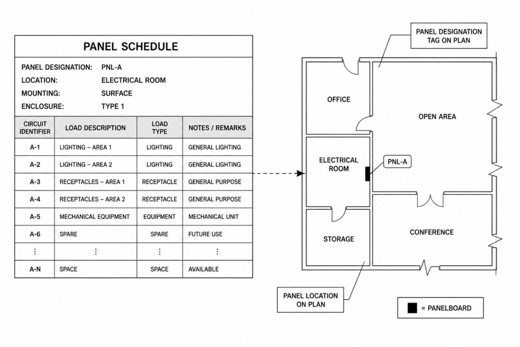
Start with the panel designation, then locate the same designation on the plan. The panel may be drawn as a wall-mounted enclosure, a floor-standing cabinet, a simplified equipment rectangle, or a symbol with a nearby label. Its graphic appearance varies by drafting convention, so the identifying text is usually more important than the outline of the symbol.
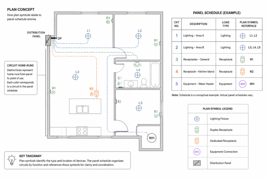
Next, follow circuit references from the schedule to the plan. A lighting circuit may connect several fixture symbols and switching arrangements. A receptacle circuit may be represented by multiple outlet symbols distributed through a room or area. Equipment circuits may terminate at a single connection point or continue to a separate equipment detail. The schedule provides the organizational description, while the plan provides location and graphical context.
Home-run lines, circuit tags, and notation near devices can be especially helpful when several circuits occupy the same area. They may indicate the panel serving the circuit, the circuit identifier, or a reference to another drawing. Always read these annotations together with the drawing legend and general notes. A symbol or abbreviation that seems familiar can have a project-specific meaning.
Reading common schedule fields
Circuit number and position
Circuit identifiers help distinguish one outgoing connection from another. The order may follow the physical arrangement of the panel, a CAD template, or a project-specific convention. Do not assume that visual row order alone explains every electrical relationship. Check whether the schedule uses paired positions, multi-pole entries, or separate sections for different circuit categories.
Description
The description should be compared with the plan and equipment naming used elsewhere in the set. Consistent wording makes coordination easier. For example, a schedule description may identify a room, an equipment tag, a lighting group, or a service function. If the wording differs between the schedule and plan, treat that as a coordination item rather than silently changing one label.
Load and calculation information
Some schedules include connected load, demand-related information, or calculated totals. These values support the design process, but their meaning depends on the project’s calculation method and the fields provided by the engineer or CAD template. A drafting review can check whether fields are populated consistently and whether totals appear to correspond to the listed circuits. It should not be used to infer an installation design from incomplete schedule data.
Spare, space, and future entries
Schedules often distinguish between unused positions, intentionally reserved positions, and circuits identified for future coordination. The exact terminology varies. Preserve the distinction shown in the source schedule because it may affect equipment coordination, panel labeling, and later design revisions.
CAD workflow for coordinating a panel schedule
- Confirm the source of truth. Identify whether the schedule is maintained in the drawing file, an electrical design application, a spreadsheet, or a coordinated document set. Avoid editing a copied table when another file controls the published information.
- Check panel naming. Compare the panel label in the schedule with labels on floor plans, riser diagrams, single-line diagrams, and equipment layouts. Look for spelling differences, missing suffixes, or inconsistent capitalization.
- Trace representative circuits. Select different circuit types, such as lighting, receptacle, and equipment connections, and follow each from schedule to plan. This helps reveal missing tags, disconnected home runs, or descriptions that no longer match the layout.
- Review drawing layers. Keep panel outlines, circuiting, annotations, symbols, and reference graphics organized on logical layers. Layer names should make it possible to isolate circuit paths or equipment information without hiding essential architectural backgrounds.
- Check annotation visibility. Review the drawing at its intended plotting scale. Circuit tags and schedule text should remain legible, while oversized symbols or overlapping notes should not obscure the plan.
- Coordinate revisions. When a circuit is moved, renamed, added, or removed, review the panel schedule and every related plan reference. A change made in only one location can create contradictory drawing information.
Useful CAD layer and block practices
A panel schedule is often inserted as a table, attributed block, external reference, or generated report. Each method has advantages. A native CAD table can be convenient for direct drafting edits. An attributed block can support consistent title information and reusable graphics. A generated schedule can reduce manual transcription when the electrical model or database is the controlled source.
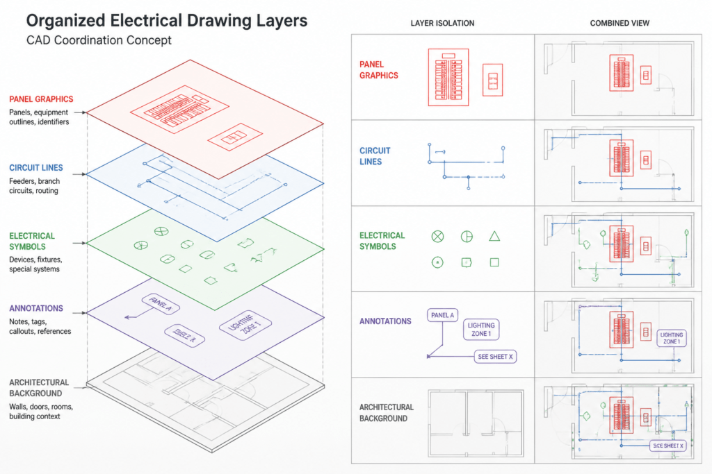
Whichever method is used, separate graphic content from project-specific data when practical. A reusable panel symbol might contain attributes for the panel label, reference designation, or equipment description, while the schedule data remains editable in its own controlled area. This reduces the risk of changing a generic block definition when only one project instance needs revision.
Use descriptive layer categories for equipment graphics, circuit lines, notes, tags, and backgrounds. Avoid relying only on color to distinguish circuit types because plotted drawings, grayscale reviews, and accessibility needs can reduce color-based clarity. Linetype, annotation, grouping, and clear labels provide additional visual structure.
Common coordination problems
- Panel labels do not match: The schedule, plan, and diagram use different names for the same equipment.
- Circuit descriptions are too vague: A label does not identify the room, equipment tag, or function needed for review.
- Plan symbols lack circuit references: Devices appear on the plan, but the reader cannot connect them confidently to the schedule.
- Schedule rows are copied without updates: A revised layout leaves obsolete descriptions or unused entries in the table.
- Graphic and data sources conflict: A manually edited CAD table differs from a schedule generated by another application.
- Notes are hidden or overwritten: Layer states, annotation masks, or external references conceal information needed for coordination.
Using a panel schedule as a reference
For drawing readers, the panel schedule is a compact index of distribution information. For CAD technicians, it is a coordination object that must stay synchronized with plans, diagrams, and equipment references. It is not enough to make the table look complete; each important entry should have a logical relationship to the rest of the drawing set.
When reviewing a panel schedule, confirm the panel identity, compare descriptions with the plan, inspect circuit references, preserve project-specific terminology, and document unresolved discrepancies. This approach improves drawing readability without assuming that a generic CAD template, symbol, or schedule can replace project engineering review.


Leave a Reply
You must be logged in to post a comment.