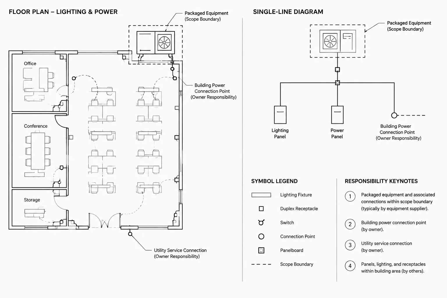
Electrical scope boundaries in CAD should clarify both the physical handoff and the division of responsibility. Well-coordinated notation helps readers distinguish project-designed work from vendor packages, owner-furnished equipment, utility interfaces, and contractor coordination requirements.
This guide explains how to represent those interfaces across plans, diagrams, schedules, details, and CAD data without relying on ambiguous notes or implying that unverified systems have been fully designed.
Electrical drawings often show systems that cross contractual and disciplinary boundaries. A piece of equipment may be selected by one party, supplied by another, connected by the electrical contractor, and controlled through a vendor package. If the drawings show only a symbol and circuit line, readers may not understand where each responsibility begins and ends.
Clear scope documentation does not replace project specifications, contracts, or coordination meetings. It does, however, help the drawing set communicate physical interfaces, connection points, and expected information exchanges. A consistent CAD workflow can make these boundaries visible without covering the plan in repetitive notes.
What Is an Electrical Scope Boundary?
A scope boundary is the documented interface between separate packages of work. It may divide responsibilities between design disciplines, contractors, equipment vendors, utilities, owners, or future project phases.
Common electrical interfaces include:
- Power supplied to equipment furnished under another package.
- Disconnecting or control components provided with packaged equipment.
- Raceway provided by one trade for cabling installed by another.
- Vendor control panels requiring power and communication connections.
- Owner-furnished equipment requiring a project electrical connection.
- Utility-owned infrastructure meeting customer-owned distribution equipment.
- Electrical provisions reserved for future equipment.
The drawing should distinguish an interface from a complete system design. Showing a connection point does not necessarily mean the electrical drawings define every component beyond that point.
Separate Physical Information from Responsibility Information
A useful drafting principle is to separate what exists physically from who provides it. Geometry answers questions such as where equipment is located and how systems connect. Notes, tags, schedules, and line conventions explain responsibility.
For example, a plan may show a vendor control panel at its coordinated location. A nearby note can identify the required electrical interface without implying that the electrical designer has documented the internal vendor wiring. On a diagram, a boundary line can separate the project distribution system from the packaged equipment while still showing the incoming connection.
Avoid relying only on phrases such as “by others.” The phrase can be ambiguous unless the responsible party or package is identified elsewhere in the documents. When the responsible party is not yet known, use a defined project term and include it in the abbreviation list, general notes, or responsibility matrix.
Choose a Consistent Graphical Method
There is no single graphical convention appropriate for every project. The important requirement is consistency across plans, diagrams, schedules, and details.
Boundary Lines and Enclosures
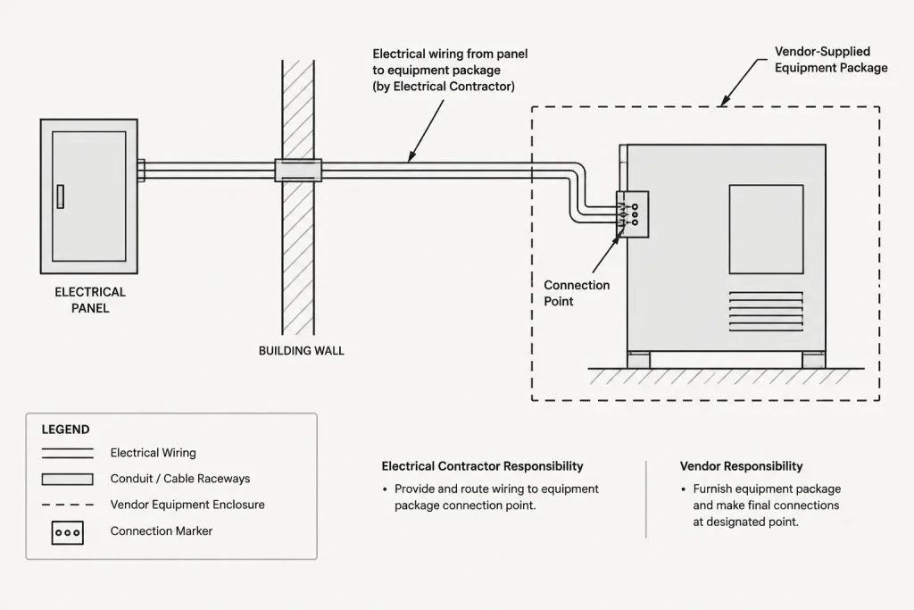
A dashed or phantom enclosure can identify the limits of a packaged system, vendor assembly, utility area, or work package. Add a clear label near the enclosure rather than expecting the linetype to explain itself. Keep the boundary visually subordinate to electrical conductors, equipment outlines, and required clearances.
Connection-Point Symbols
A distinct connection-point marker can identify where project wiring terminates at equipment supplied under another scope. This is especially useful when the equipment contains internal distribution or control components that are not fully represented in the project CAD files.
The marker should have one defined meaning. Do not use the same graphic for a terminal, splice, continuation point, and contractual interface unless accompanying labels make the distinction unmistakable.
Lineweight and Screening
Equipment outside the electrical construction scope may be screened or shown with a lighter plot hierarchy while the electrical connection remains prominent. Test the result in the plotted output. Excessive screening can make essential coordination geometry disappear, while heavy background outlines can compete with the electrical work.
Keynotes and Scope Tags
Keynotes are effective when several similar interfaces occur on a plan. A short scope tag can direct readers to a defined note explaining the division of work. Keep tag placement close enough to the relevant object that the association remains clear after backgrounds change.
Coordinate Scope Across Drawing Types
A scope boundary shown on only one sheet can create contradictions elsewhere. Each drawing type should communicate the same interface at an appropriate level of detail.
| Drawing type | Useful scope information | Common drafting risk |
|---|---|---|
| Floor plan | Equipment location, connection point, local disconnect or control interface, and scope keynote | A circuit line appears to serve the entire package without identifying the termination point |
| Single-line diagram | Source, feeder relationship, ownership transition, and downstream system boundary | Vendor components are drawn as though they are fully designed by the project team |
| Control or interconnection diagram | Signal interfaces, terminal references, and divisions between project and packaged controls | Internal control logic is inferred or invented without vendor information |
| Equipment connection schedule | Equipment ID, electrical interface, source reference, and responsibility note | Schedule language conflicts with plan notes |
| Detail or elevation | Physical handoff location, mounting relationship, and coordinated routing approach | A typical detail is applied where the actual equipment arrangement differs |
The amount of information does not have to be identical on every sheet. It should, however, lead readers to the same conclusion about the boundary.
Use a Responsibility Matrix for Repeated Interfaces
When a project includes many packaged systems, a responsibility matrix can reduce repetitive plan notes. The matrix may identify who furnishes, installs, connects, controls, or coordinates each major item. Its column headings should use terms defined for the project rather than unexplained abbreviations.
A matrix works best as a navigation and coordination tool, not as a substitute for all graphical information. The plan must still show where the interface occurs. The diagram must still show how the equipment relates to the distribution or control system.

Before creating a new matrix, confirm whether responsibility is already defined in another project document. Duplicate tables maintained by different teams can drift apart during revisions.
Build Scope Intelligence into CAD Objects
Block attributes and object data can help maintain scope information when used carefully. Useful fields may include equipment ID, package designation, furnishing party, connection responsibility, schedule reference, or vendor-document status.
Do not place every field visibly beside every symbol. Keep essential plan information visible and retain supporting data for schedules or quality-control reviews. Attribute values should use controlled terminology so that “vendor,” “equipment supplier,” and several abbreviations do not become accidental categories for the same responsibility.
Layers can also support scope review, but they should not carry the entire meaning. A reader viewing a PDF or grayscale print may not have access to layer names or colors. Visible labels and legends remain necessary where scope affects interpretation.
Document Unknown and Pending Vendor Information
Early drawings often precede final equipment selections. The CAD set should identify unresolved interfaces without presenting assumptions as verified facts.
Practical methods include:
- Using a clearly defined placeholder equipment outline.
- Marking connection data as pending confirmation.
- Adding a coordination note tied to the specific equipment tag.
- Tracking required vendor drawings in a separate coordination log.
- Avoiding detailed internal wiring until verified information is available.
Generic CAD blocks are useful for layout development, but their terminals, connection locations, and internal arrangements should not be treated as manufacturer data. Replace or revise placeholders when verified project information becomes available.
A CAD Workflow for Scope-Boundary Documentation
-
Identify interface equipment. Review the equipment list, backgrounds, diagrams, and consultant information for systems involving more than one responsible party.

-
Define project terminology. Establish consistent names for work packages and responsibilities. Coordinate those terms with the project documentation rather than creating isolated CAD shorthand.
-
Mark the physical handoff. Show the location where power, raceway, cable, controls, or communications meet the other system.
-
Add a visible scope reference. Use a keynote, boundary label, connection marker, or schedule reference that remains understandable in the plotted drawing.
-
Coordinate related views. Check the floor plan, diagram, schedule, detail, and equipment list for matching equipment IDs and compatible descriptions.
-
Track unresolved information. Record missing vendor or utility information outside the drawing as an actionable coordination item, while noting its effect in the drawing where necessary.
-
Review the published output. Confirm that screening, linetypes, tags, and boundary labels remain legible in PDF and print formats.
Common Scope-Documentation Errors
- Unqualified “by others” notes: The drawing does not identify which party or package is responsible.
- Conflicting documents: A plan note, schedule entry, and diagram assign different responsibilities.
- Over-detailed vendor systems: Unverified internal components are drawn as finalized design information.
- Layer-only communication: Scope meaning disappears when layers are combined, exported, or printed without color.
- Missing termination point: A raceway or cable enters equipment, but the intended handoff is not shown.
- Stale placeholders: Generic blocks and preliminary notes remain after verified equipment information is received.
- Boundary clutter: Large enclosures and dense notes obscure the electrical system they are intended to clarify.
Final Drawing Review
During quality control, follow each cross-scope connection from its source to its endpoint. Confirm that a reader can identify the equipment, understand the physical interface, locate related information, and distinguish project-designed work from vendor- or owner-defined work.
Scope boundaries should make the drawings easier to interpret, not attempt to restate the entire contract. The strongest CAD documentation combines concise visible notation with coordinated schedules, diagrams, and project terminology. Every boundary should communicate where the interface occurs, what is being connected, and where the reader should look for the remaining responsibility information.
A Practical Pattern for Scope Notes
A useful scope note identifies the object, required interface, responsibility distinction, and related document reference. This structure is more informative than a standalone phrase such as by others, which may leave the responsible package and precise handoff unclear.
Keep each note limited to what the drawing needs to communicate. Contractual interpretation, procurement requirements, and detailed execution language should remain coordinated with the governing project documents.
Test Each Boundary from the Reader’s Viewpoint
- Object: Can the reader identify the equipment or system associated with the boundary?
- Interface: Is the physical termination or connection point visible?
- Responsibility: Does the notation distinguish furnishing, installation, connection, control, or coordination duties where relevant?
- Reference: Can the reader locate the related schedule, diagram, detail, note, or vendor information?
- Status: Is preliminary or pending information clearly distinguished from verified project data?
Managing Scope Changes During Revisions
Responsibility assignments can change as equipment selections, procurement packages, and coordination decisions develop. Treat scope notation as coordinated project information rather than static annotation.
When an interface changes, review every location where the assignment may appear. This can include plan keynotes, diagram labels, equipment schedules, block attributes, responsibility matrices, legends, and coordination logs. Updating only the most visible plan note can leave conflicting instructions elsewhere in the set.
CAD standards can support this review by using controlled terminology and searchable attributes. Published sheets must still communicate the boundary without depending on hidden object data, layer names, or color alone.
Frequently Asked Questions
What does “by others” mean on an electrical drawing?
It indicates that work is outside the scope represented by the immediate note or drawing package. Because the phrase does not identify a responsible party by itself, it should be connected to defined project terminology, a responsibility matrix, or another coordinated reference.
Should vendor equipment be shown on the electrical plan?
Vendor equipment may be shown when its location and interfaces are needed for electrical coordination. Its internal wiring or components should not be presented as verified design information unless supported by approved project data.
Can a CAD layer define the responsibility boundary?
A layer can assist editing, filtering, and quality control, but it should not be the only method. Layer information may be unavailable in a PDF, print, export, or combined model. Visible labels, symbols, notes, or legends should preserve the intended meaning.
What is the difference between a connection point and a scope boundary?
A connection point identifies where systems physically meet or terminate. A scope boundary explains how responsibility changes at or around that interface. The same location may represent both concepts, but the drawing should define them clearly.
How should pending vendor information be documented?
Use a clearly identified placeholder, status note, or coordination reference tied to the affected equipment. Avoid depicting assumed terminal arrangements, internal controls, or connection details as verified information.
Where should repeated responsibility assignments be recorded?
A coordinated responsibility matrix or equipment connection schedule can reduce repeated plan notes. The drawings should still show the physical interface and provide a clear reference to the supporting information.












Leave a Reply
You must be logged in to post a comment.