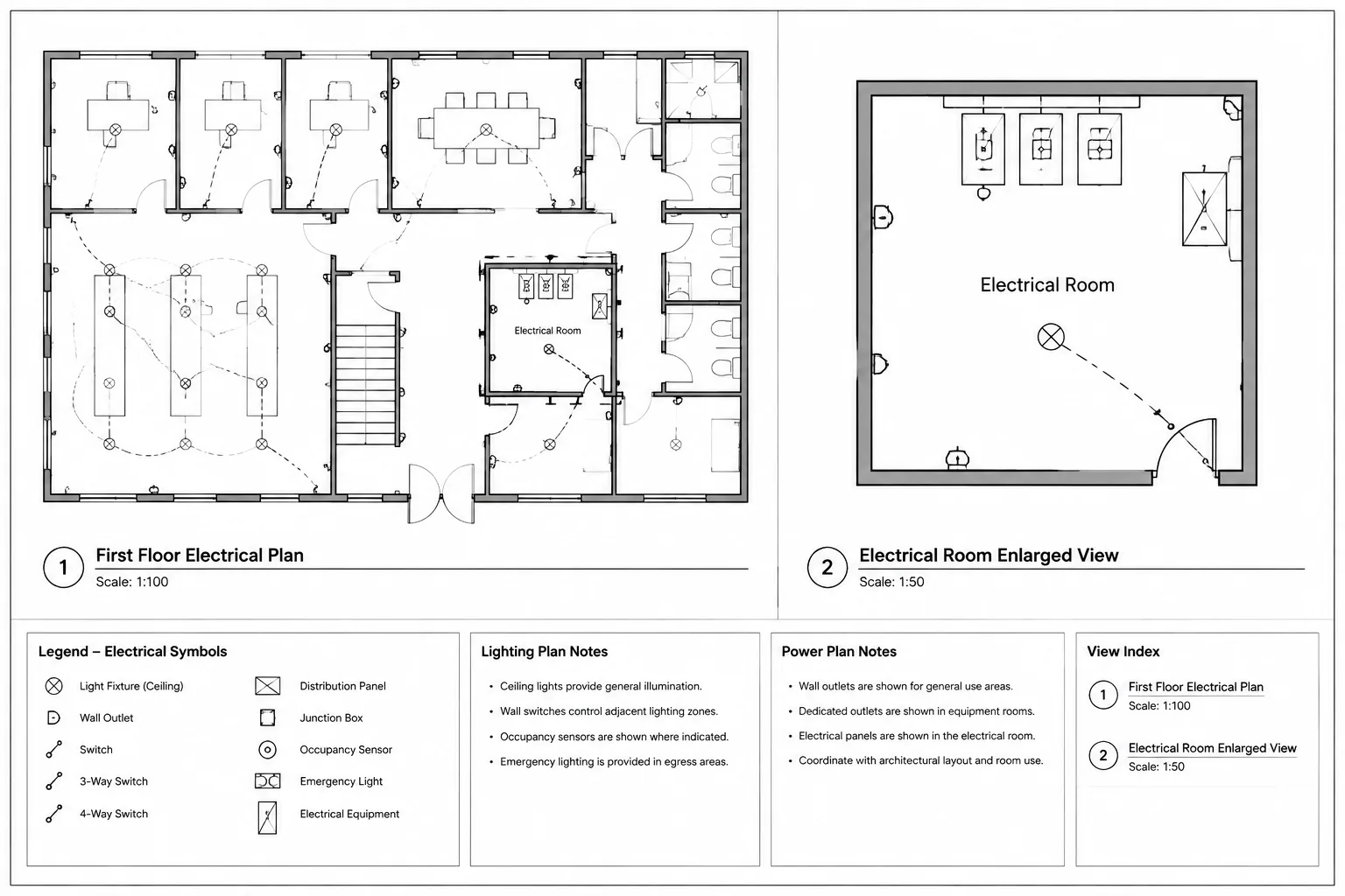
Electrical CAD scale indicators must agree with the view they describe. This guide explains how viewport settings, written scale labels, graphic scales, annotation behavior, and not-to-scale designations work together across an electrical drawing set.
The goal is not to make printed drawings measurable for critical requirements. It is to present each view clearly while using dimensions, labels, schedules, and coordinated references to communicate verified design intent.
Drawing scale is more than a title placed beneath a viewport. In an electrical drawing set, it affects symbol readability, annotation, background coordination, detail references, and how reliably a reviewer can interpret a printed or digital sheet. Scale problems often appear when a model is correct but the viewport, title, graphic scale, or annotation settings do not agree.
A dependable electrical CAD drawing scale workflow separates model geometry from sheet presentation. Equipment footprints, room backgrounds, routing, and other physical objects are generally drawn at their intended size in model space. Paper space then controls how much of that model appears on a sheet and how large it appears when plotted. Notes, dimensions, symbols, and viewport titles must be coordinated with that presentation.
What Drawing Scale Communicates
A scale label describes the relationship between model geometry and its plotted representation. It helps readers understand the level of detail intended for a view. A broad site plan, a floor plan, an enlarged electrical room plan, and an equipment detail may each require a different presentation scale.
Scale does not establish design requirements by itself. It also does not replace written dimensions, equipment data, or coordinated connection information. Readers should not need to measure a printed line to determine a critical installation location.
For drafting purposes, treat the following as separate but related elements:
- Model geometry: Physical objects and backgrounds represented at their intended project size.
- Viewport scale: The paper-space setting that controls the displayed size of model geometry.
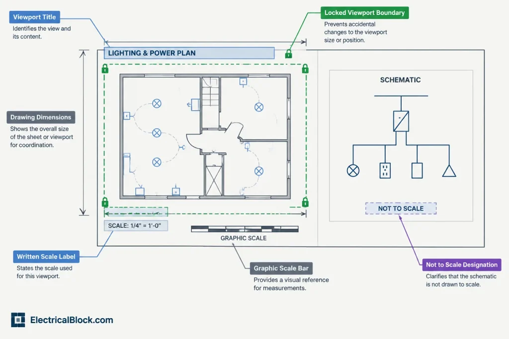
- Scale label: The text identifying the intended scale of the view.
- Graphic scale: A plotted bar that provides a visual scale reference when the sheet is reproduced at the intended size.
- Annotation scale: A setting or workflow used to keep text and symbols readable across differently scaled views.
- Dimensions: Explicit documentation of required distances, offsets, or extents.
Start with Correct Model-Space Geometry
Before adjusting a viewport, confirm that the underlying electrical and architectural geometry uses a consistent unit convention. A viewport can make incorrectly sized geometry look plausible, especially when there is no known reference object nearby.
Use a verified background feature, grid relationship, or documented dimension to check the model. Do not assume that an imported file is correctly scaled merely because it aligns visually with another reference. Linked files, converted PDFs, survey data, vendor drawings, and legacy details may have different unit assumptions.
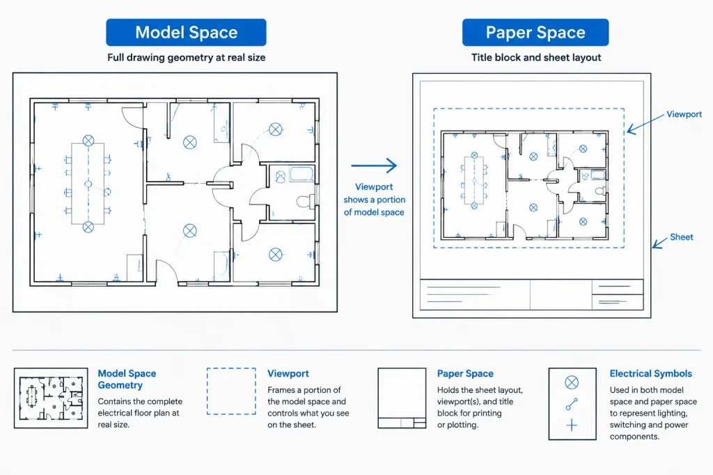
CAD blocks also require attention. A receptacle symbol or home-run marker may be a schematic plan symbol intended for legibility rather than a physical footprint. In contrast, a switchboard outline, transformer footprint, or floor box opening may represent actual geometry. The drafting team should know which blocks are diagrammatic and which are dimensional.
Coordinate the Viewport and Its Title
Each scaled view should have a clear relationship between its viewport settings and its displayed title. Changing the viewport without revising the title creates a misleading sheet even when the model itself remains correct.
A practical viewport workflow
- Create the viewport from an approved sheet layout rather than copying an unexplained viewport from an older project.
- Set the required view extent and presentation scale.
- Center the relevant work without introducing unnecessary empty space.
- Verify that symbols, notes, and circuiting remain legible.
- Update the scale text in the view title.
- Lock or otherwise protect the viewport from accidental zoom changes.
- Plot a test sheet and inspect the output rather than relying only on the CAD screen.
Viewport titles are easier to maintain when their information is controlled consistently. A title may identify the view name, detail or plan designation, source sheet reference, and scale. Whether these items are separate objects or part of an attributed title block, the project should use one repeatable convention.
Choose Scale Based on Information Density
The appropriate scale depends on what the view must communicate. A plan with only major equipment locations may remain understandable at a relatively broad presentation. A congested electrical room showing equipment footprints, working areas, connection points, tags, and routing may require an enlarged plan.
Do not solve every readability problem by enlarging symbols. Oversized symbols can overlap walls, equipment, and other systems while hiding the actual congestion. First determine whether the drawing needs an enlarged view, simplified background, improved annotation placement, or a separate detail.
| View condition | Useful drafting response |
|---|---|
| Tags and circuit lines overlap | Reposition annotations, reduce unnecessary background detail, or create an enlarged plan. |
| Equipment footprints cannot be distinguished | Use a larger-scale view and coordinate plan, elevation, or section references. |
| A detail contains mostly diagrammatic information | Consider marking it not to scale and rely on labels and dimensions. |
| The viewport has large unused areas | Reframe the view, but do not change scale solely to fill the sheet. |
| Symbols appear different across sheets | Review annotation settings and block behavior before editing source geometry. |
Use Graphic Scales Carefully
A graphic scale is useful because it enlarges or reduces with the printed view. However, it is not a guarantee that every copy of a drawing remains measurable. PDF print settings, page fitting, scanning, image conversion, and placement into another document can alter the final output.
Place a graphic scale where it is clearly associated with the correct view. On a sheet containing several views at different scales, a single general graphic scale can be ambiguous. Each scaled view should have its own clearly related indicator when a graphic scale is part of the project convention.
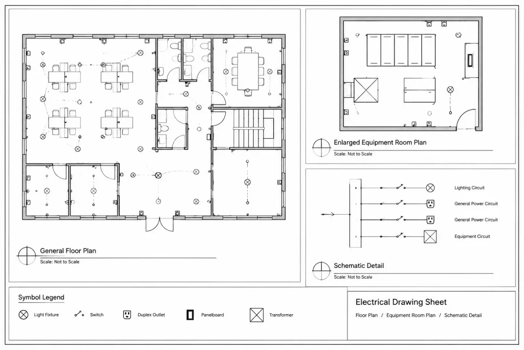
A graphic scale should agree with the viewport and written scale label. During quality control, compare all three rather than checking only that a bar exists. A copied graphic scale can retain the wrong size or label after a viewport changes.
When to Mark a View Not to Scale
A not-to-scale designation is appropriate when a view communicates relationships, sequence, or typical arrangement rather than measurable geometry. Common examples may include schematic diagrams, conceptual risers, wiring relationships, and certain typical installation details.
Marking a view not to scale does not remove the need for clarity. The view still needs consistent symbols, complete labels, understandable connections, and enough written information to express its purpose. If a location, offset, opening, or equipment arrangement is critical, document it with verified dimensions or reference a coordinated plan, section, schedule, or manufacturer-specific submittal.
Avoid using not-to-scale labels as a remedy for poorly constructed geometry. If a detail is intended to show a dimensional arrangement, correct the geometry and document the necessary dimensions instead of relying on the designation to excuse inconsistencies.
Handle Multiple Scales on One Sheet
Electrical sheets often combine a main plan with enlarged rooms, sections, or typical details. This is workable when each view has an independent title and the boundary between views is obvious.
Keep annotations associated with their own viewport. Notes positioned between views can appear to apply to both. Likewise, avoid placing a graphic scale in a shared title area unless its intended view is unmistakable.
When an enlarged plan repeats information from a main plan, decide which view governs the detailed documentation. Use callouts and references so readers understand where to find additional information. Coordinate device tags, equipment identifiers, and status notation between the views rather than allowing the enlargement to become a disconnected duplicate.
Dimensions Should Carry Critical Information
Scale supports visual understanding, but dimensions communicate explicit requirements. Electrical drawings may need dimensions for equipment locations, coordinated openings, connection points, sleeves, pads, access zones, or interfaces with architectural features. The required extent depends on project scope and documentation responsibilities.
Dimensions should reference stable, coordinated features whenever possible. A dimension tied to temporary furniture, an unverified background line, or a movable annotation does not create reliable design intent. Before issue, confirm that dimension origins and endpoints still correspond to current geometry.
Do not dimension a symbol simply because it looks like a physical object. Determine whether the symbol represents an approximate device location, a diagrammatic marker, or an actual equipment footprint. Add notes or references where the distinction may not be obvious.
Electrical Drawing Scale Quality-Control Checklist
- Confirm that model geometry uses the project unit convention.
- Check imported backgrounds and referenced files against known information.
- Verify that each viewport scale matches its written title.
- Protect finalized viewports from accidental zoom or scale changes.
- Confirm that graphic scales correspond to the correct views.
- Review annotative text, symbols, dimensions, and leaders at plotted size.
- Check that enlarged views and main plans use coordinated identifiers.
- Mark schematic or relational views as not to scale when appropriate.
- Use verified dimensions instead of expecting readers to scale critical locations.
- Inspect the issued PDF or print output, not only the source CAD file.
Build Scale Checks into the Documentation Workflow
Scale coordination should occur whenever a view is created, moved to another sheet, enlarged, reduced, or copied from another project. It should also be checked after background updates because a replacement reference file may use a different insertion unit, origin, or drawing convention.
A final review should compare model geometry, viewport properties, titles, graphic scales, and plotted annotation as one system. This approach catches the common situation in which each individual object appears reasonable but the complete sheet communicates conflicting information.
Well-managed scale indicators make electrical drawings easier to navigate and reduce the risk of misreading a plan. More importantly, they reinforce a sound documentation principle: use scale to organize and present information, while using dimensions, labels, schedules, and coordinated references to communicate verified design intent.
Managing Scale Information During Drawing Revisions
Scale coordination is also a revision-control issue. A view may begin correctly and become misleading after it is copied, reframed, moved to another sheet, or replaced by an enlarged view. The visible geometry may still look acceptable even though the viewport property, title, graphic scale, and annotation behavior no longer agree.
When revising a sheet, treat the viewport and its associated documentation as one controlled group. Review the view boundary, title, scale label, graphic scale, detail reference, and nearby notes together. If the view is changed to not to scale, remove or revise indicators that imply measurable plotted geometry.
Record Intent in the CAD Workflow
Consistent layer names, viewport naming, title-block attributes, and review notes can help the drafting team understand how a view is intended to behave. A clear workflow is especially valuable when several contributors edit the same drawing set or when files are exchanged between design disciplines.
- Identify dimensional content: Distinguish physical equipment outlines and coordinated openings from diagrammatic symbols.
- Associate indicators with views: Keep titles and graphic scales close enough to prevent ambiguity.
- Control copied content: Recheck scale-related objects after reusing a detail or sheet layout.
- Review final output: Confirm that the issued document communicates the same intent as the source CAD file.
A reliable scale workflow makes drawing changes easier to audit. It also helps reviewers recognize whether a view is intended for spatial coordination, diagrammatic explanation, or general reference.
Frequently Asked Questions About Electrical CAD Scale Indicators
Should a graphic scale replace the written viewport scale?
No. A graphic scale can supplement a written scale label, but both should correspond to the actual viewport. The project convention should make their relationship to the view unmistakable.
Why can a correctly drawn model appear at the wrong scale?
The problem may be in the viewport setting, imported file units, insertion behavior, plotting configuration, or document reproduction. Check the source geometry and sheet presentation separately.
When should an electrical detail be marked not to scale?
Use a not-to-scale designation when the detail communicates relationships, sequence, or a typical arrangement rather than measurable geometry. Critical locations and interfaces still require verified dimensions or coordinated references.
Can symbols be enlarged to improve readability?
Diagrammatic symbols may use annotation behavior that keeps them legible, but dimensional equipment outlines should not be altered merely to improve appearance. Confirm the purpose of the block before changing it.
What should be checked after changing a viewport?
Review the viewport title, written scale, graphic scale, annotation placement, dimensions, callouts, view references, and final plotted output. Protect the viewport after the review to reduce accidental changes.
Should readers measure electrical locations from a printed drawing?
Critical locations should be communicated through verified dimensions, labels, schedules, or coordinated references rather than relying on measurements taken from a print or screen.












Leave a Reply
You must be logged in to post a comment.