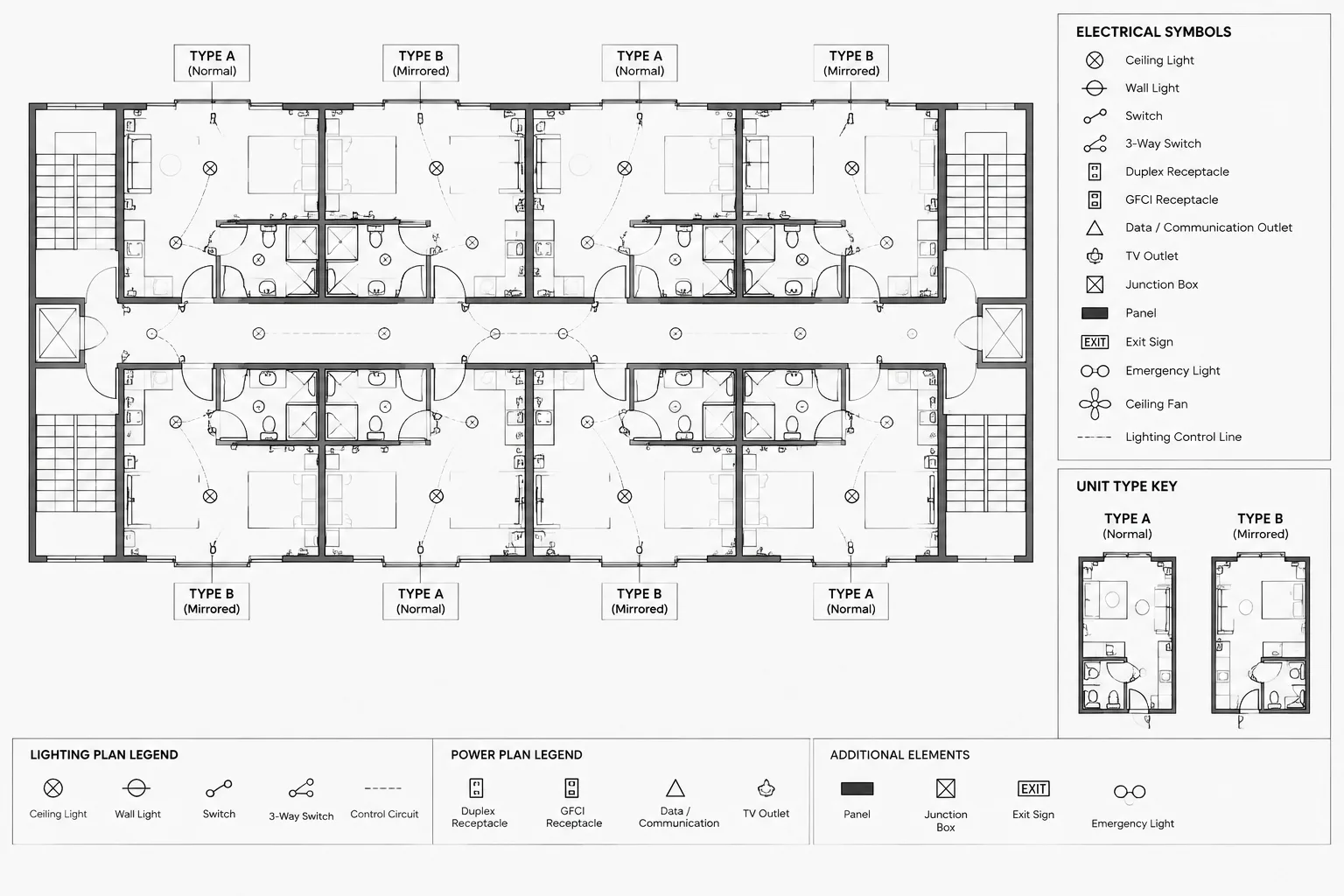
Repeated unit electrical plans in CAD require more than duplicating a completed room layout. The drafting system must preserve common geometry while keeping mirrored conditions, circuit references, annotations, and local variations visible and traceable.
This guide explains how to organize typical layouts, distinguish type-level content from instance-level data, document exceptions, and review repeated units without assuming that similar architectural plans are electrically identical.
Buildings with repeated rooms or dwelling units can appear simple to draft: create one electrical layout, copy it throughout the floor, and revise the copies as needed. In practice, that approach often produces inconsistent symbols, outdated circuit information, and exceptions that are difficult to find during review.
A more reliable workflow separates the typical electrical design from its individual floor-plan instances. The drawings should communicate which units share a typical layout, how mirrored or rotated versions are handled, and where project-specific conditions override the typical information.
This approach is useful for apartments, hotels, dormitories, patient rooms, classrooms, offices, retail bays, and other projects with repeating electrical arrangements. It is a documentation strategy, not a substitute for project-specific design and code review.
Start with an Architectural Unit-Type Map
Before placing electrical symbols, identify how the architectural drawings define repeated spaces. A building may use similar-looking units that differ in wall length, door swing, casework, ceiling layout, accessibility features, or equipment arrangement. Treating these as one type merely because their footprints look similar can conceal important electrical differences.
Create a working list that relates each unit instance to an architectural type. Record useful distinctions such as:
- Unit or room number
- Architectural unit-type designation
- Floor or building area
- Normal, mirrored, or rotated orientation
- Ceiling or equipment variation
- Electrical exception status
- Applicable enlarged plan or detail reference
This list can become a CAD table, a spreadsheet used for coordination, or a controlled project database. Its main purpose is to prevent assumptions about which spaces are truly identical.
Choose a Documentation Strategy
Repeated unit electrical plans are commonly documented through typical enlarged plans, direct floor-plan layouts, or a combination of both. The right method depends on drawing scale, project complexity, and the number of exceptions.
| Method | Best use | Main coordination concern |
|---|---|---|
| Typical unit plan | Many units share the same arrangement | The overall plan must clearly identify where the type applies |
| Direct floor-plan drafting | Instances contain frequent differences | Copied layouts can drift apart during revisions |
| Referenced or linked unit file | A controlled repeated layout is maintained separately | File paths, clipping, orientation, and issue status require management |
| Hybrid approach | Typical information is repeated with local exceptions | Users must distinguish inherited information from overrides |
A typical plan should not force readers to guess whether symbols shown on the overall floor plan are diagrammatic placeholders or complete device layouts. State the relationship directly with type tags, callouts, notes, or a unit matrix.

Build the Typical Layout Around Stable Geometry
Use architectural features that are unlikely to move independently as references for electrical symbol placement. Walls, door openings, fixed casework, equipment zones, and reflected ceiling elements are generally more useful than arbitrary coordinates.
Organize the typical layout so that different information categories remain controllable. Depending on office standards, separate layers or data fields may be used for:
- Lighting fixtures and lighting-control devices
- Receptacles and small-power outlets
- Dedicated equipment connections
- Communications and low-voltage devices
- Circuiting graphics and home-run information
- Device tags, mounting references, and notes
- Unit boundaries and type identifiers
- Exception clouds or coordination markers
Keep design information separate from architectural background geometry. Electrical content should remain editable and reviewable when the architectural unit plan changes.
Handle Mirrored Units Deliberately
A mirrored architectural plan does not automatically produce a correct mirrored electrical design. Graphic geometry may reverse successfully while text, attributes, circuit relationships, and directional symbols do not.
After mirroring a unit layout, review each of the following:
- Text orientation and attribute readability
- Door-side switch locations and control intent
- Fixture positions relative to ceiling features
- Equipment connection points and service sides
- Receptacle relationships to casework and furniture
- Panel or source references
- Circuit tags and home-run destinations
- Detail callouts, section marks, and directional arrows
Where mirrored units are common, consider maintaining explicit normal and mirrored type variants. Names such as “Type A” and “Type A Mirror” are clearer than relying on a visually flipped block with no separate designation. Follow the project’s established naming convention and coordinate it with the architectural type names.
Separate Layout Geometry from Instance-Specific Data
The physical arrangement may repeat, but not every piece of electrical data should be copied unchanged. Different unit instances may connect to different panels, circuits, control zones, communication rooms, or distribution paths.
A useful division is:
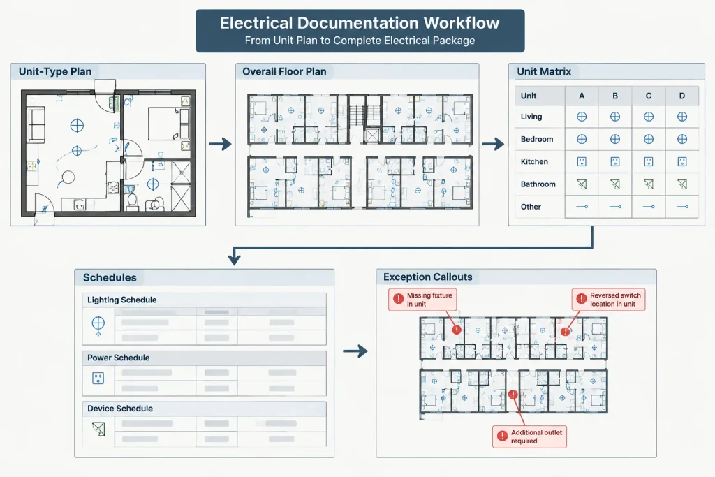
- Type-level information: symbol arrangement, device relationships, typical notes, and common connection intent.
- Instance-level information: room number, panel reference, circuit designation, equipment identifier, system zone, and local exception.
This distinction is especially important when a typical unit appears on several floors. A copied home-run label can look correct graphically while pointing to the wrong distribution source. Where possible, store instance-specific information in controlled attributes, schedules, or clearly isolated annotation rather than embedding it permanently in repeated geometry.
Document Exceptions Without Breaking the Typical Plan
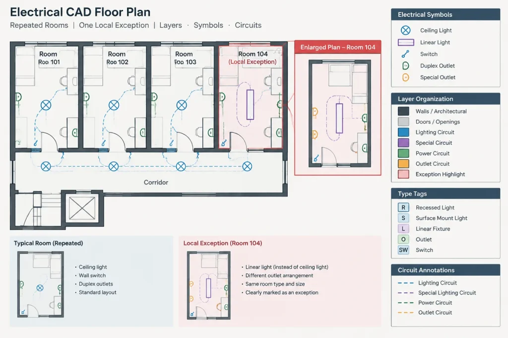
Not every variation warrants a new unit type. A limited change may be documented as an exception if the base layout remains recognizable. Examples include a relocated device caused by casework, a different equipment connection, or a ceiling coordination adjustment.
Use a consistent exception method, such as:
- A keyed note attached to the affected unit
- An exception tag linked to a schedule
- A local enlarged plan
- A clearly bounded override area
- A separate subtype when variations become substantial
Avoid vague notes such as “similar” unless the drawing identifies what differs. Readers should be able to determine whether the exception changes location, quantity, circuiting, equipment, controls, or another documented condition.
When an Exception Should Become a New Type
Create a separate electrical type when repeated overrides make the base type difficult to interpret. A new type is also appropriate when the variation affects several coordinated systems or when the architectural layout has materially changed. Maintaining too few types can be just as confusing as maintaining too many.
Use Blocks, Groups, and References with Care
Different CAD methods offer different levels of control. A block can make repeated geometry easy to update, but nested attributes and mirrored instances require careful testing. A group can assist selection without enforcing a common definition. An external reference can centralize updates, but it introduces file-management and visibility considerations.
Whichever method is selected, establish these rules before broad duplication:
- Define a meaningful insertion or reference point.
- Use a documented orientation.
- Keep annotation behavior predictable.
- Identify which elements may be edited locally.
- Prevent accidental edits to the architectural background.
- Track the current approved drafting source for each unit type.
Do not explode repeated-unit content simply to make a quick local change without recording the exception. Once an instance loses its relationship to the controlled type, future revisions may no longer reach it.
Coordinate Overall Plans, Enlarged Plans, and Schedules
The overall floor plan should tell readers which typical plan applies to each unit. The enlarged unit plan should provide the detail that cannot be read clearly at the overall scale. Schedules and diagrams should carry data that would overcrowd either plan.
Check that unit-type tags do not conflict with room numbers, equipment tags, or architectural apartment designations. If the electrical naming system differs from the architectural system, provide an explicit cross-reference rather than expecting users to infer the relationship.
Also verify that symbols are not unintentionally duplicated between the overall plan and the enlarged plan. If both views show electrical content, define which view controls location and which provides contextual or circuiting information.
Perform a Unit-by-Unit Quality-Control Pass
Automated block counts can help, but repeated layouts need visual and data-based review. A practical checking sequence includes:
- Compare the unit-type map with the latest architectural plan.
- Confirm every unit instance has a type or an identified exception.
- Review mirrored and rotated instances separately.
- Check that text and attributes remain readable.
- Verify instance-specific circuit and source references.
- Compare device counts against the typical plan and exception list.
- Confirm ceiling devices align with the coordinated ceiling background.
- Search for exploded, orphaned, or outdated unit layouts.
- Plot the sheets and review them at the intended output scale.
A unit matrix is particularly valuable during revisions. When an architectural type changes, the matrix helps identify every affected floor-plan instance, mirrored variant, enlarged plan, schedule entry, and related diagram.
Create a Workflow That Supports Revision
The greatest benefit of a repeated-unit strategy is not faster initial copying. It is controlled revision. A well-structured drawing set makes it possible to answer three questions quickly: Which layout is the current typical design? Where is it used? Which instances intentionally differ?
Keep type names stable, record exceptions visibly, and separate common geometry from local data. Before issuing drawings, verify all symbols, connections, annotations, and layouts against the current project requirements. Repetition should reduce drafting effort without hiding the real differences that matter to construction and coordination.
A Practical Type–Instance–Exception Hierarchy
A useful way to audit repeated-unit documentation is to classify every item as type information, instance information, or an exception. This classification clarifies where an edit belongs and helps prevent local project data from being embedded in shared geometry.
- Type information belongs to the controlled typical layout and should change wherever that type is used.
- Instance information identifies a particular occurrence, such as its room designation, source reference, circuit annotation, or system relationship.
- Exception information records an intentional departure from the type and should remain visible during review and revision.
Before editing a repeated layout, determine which category the change affects. A device relocation caused by a revision to the typical casework may require an update to the shared type. The same relocation caused by a condition in only one room may instead require a documented exception. If the distinction is unclear, copied drawings can diverge without an obvious record of why.
Review the Drawing as a Reader Will Use It
Quality control should test the communication path as well as the CAD geometry. Starting from the overall plan, a reviewer should be able to identify the assigned unit type, locate the controlling enlarged plan, recognize mirrored or rotated variants, and find any local override. The same path should work in reverse when a typical plan changes and affected instances must be located.
Plot review is important because layer states, clipped references, annotation visibility, and overlapping symbols may appear acceptable in the model while becoming ambiguous on the issued sheet. Confirm that the documentation hierarchy remains understandable without relying on unwritten knowledge held by the original drafter.
Use Change Classification During Coordination
When updated architectural backgrounds arrive, sort changes by their documentation effect rather than treating every revision alike. A background change may affect the typical electrical geometry, create a mirrored variant, alter only instance-specific data, or introduce a local exception. Recording that decision in the unit matrix or project review log gives the team a traceable reason for each drawing update.
This approach also supports handoff between drafters. A new team member can identify the controlled source, understand which instances inherit it, and recognize where local edits are intentional. The result is not merely a cleaner CAD file; it is a drawing set that makes repetition and variation equally clear.
Frequently Asked Questions
Should every repeated room use the same electrical CAD block?
Only when the rooms genuinely share the same controlled geometry and annotation behavior. Differences in orientation, casework, ceilings, equipment, or source references may require a separate variant or instance-level information.
Is mirroring a typical unit enough to create a mirrored electrical plan?
No. Mirroring may reverse geometry without correctly updating text, attributes, directional symbols, control intent, equipment relationships, or circuit references. The mirrored result requires a dedicated review and may be clearer as an explicitly named variant.
What information should remain outside the typical layout?
Data that changes by location should generally remain instance-specific. Examples include room identifiers, panel or source references, circuit designations, system zones, equipment identifiers, and local exception notes.
When should a local exception become a separate unit type?
Create a separate type when overrides are repeated, affect several coordinated systems, or make the base layout difficult to interpret. A separate type may also be appropriate when the architectural arrangement has changed enough that the original typical plan no longer communicates the condition clearly.
How can drafters find outdated repeated units?
Compare the current architectural type map with the electrical unit matrix, inspect mirrored and rotated variants, review controlled references or block definitions, and search for exploded or orphaned geometry. Plot review can reveal visibility and annotation problems that are less obvious in the model.
Which drawing should control device location?
The drawing set should state that relationship explicitly. If both an overall plan and an enlarged typical plan show electrical content, notes, callouts, or drawing conventions should identify which view controls location and which view provides context or circuiting information.












Leave a Reply
You must be logged in to post a comment.