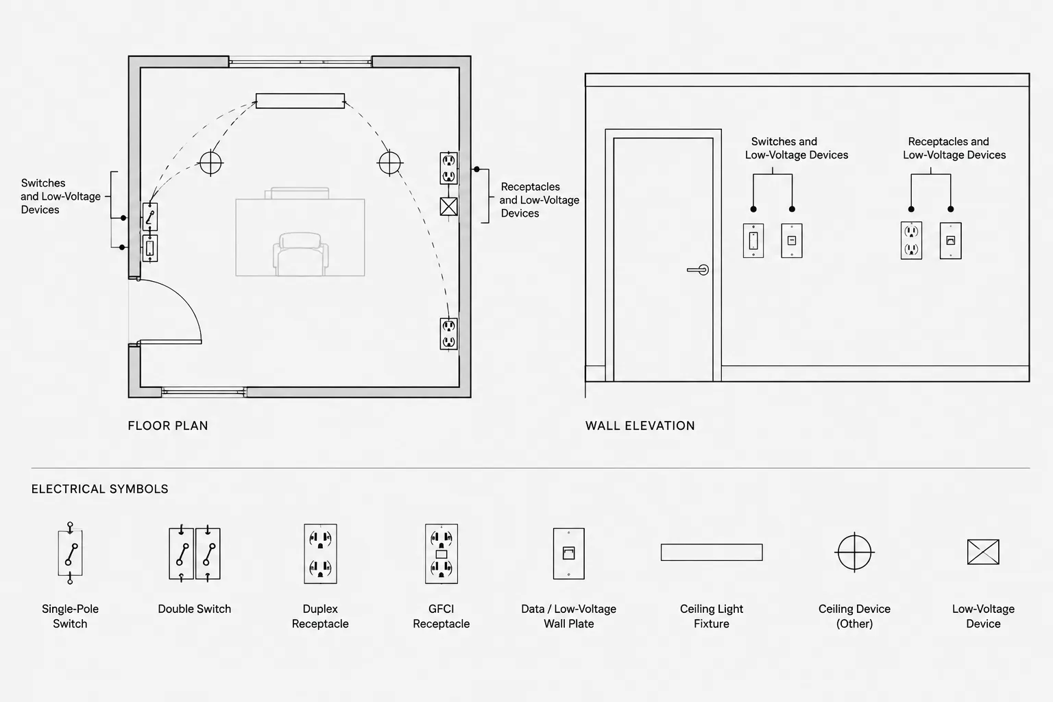
Multi-device wall assemblies in electrical CAD must communicate association without overstating the physical construction. Symbols for switches, receptacles, controls, and low-voltage outlets may share a wall location while remaining separate in scope, enclosure, faceplate, or documentation responsibility.
This guide explains how to represent those relationships with grouping graphics, composite blocks, assembly tags, schedules, elevations, layers, and cross-references. The emphasis is on readable drawing intent and coordinated documentation rather than unverified installation detail.
Wall locations often contain more than one electrical device. A doorway may have lighting controls, an occupancy sensor interface, and a low-voltage control station. A workstation wall may combine power, data, and audiovisual connections. If each symbol is placed independently, the plan may suggest separate locations even when the design intends a coordinated assembly.
Multi-device wall assemblies in CAD require more than placing several blocks close together. The drawings should communicate which devices are associated, whether they share a faceplate or enclosure, which discipline provides each component, and where additional information can be found. The goal is not to depict hidden construction that has not been verified. It is to document design intent clearly enough for coordination, review, and later detailing.
What Is a Multi-Device Wall Assembly?
A multi-device wall assembly is a coordinated group of devices intended for the same general wall location. Depending on the project, it may include:
- Lighting switches, dimmers, scene stations, or other control devices
- Power receptacles and specialty outlets
- Data, telephone, audiovisual, or control outlets
- Thermostats, sensors, or building-control interfaces
- Access control, intercom, or signaling devices
- Blank positions or provisions reserved for future devices
Graphical grouping does not automatically mean that every device occupies one box, one faceplate, or one trade-provided assembly. Those physical relationships must come from verified project information. CAD grouping should therefore distinguish between a shared location, a shared mounting arrangement, and a confirmed common assembly.
Why Closely Spaced Symbols Can Be Misleading
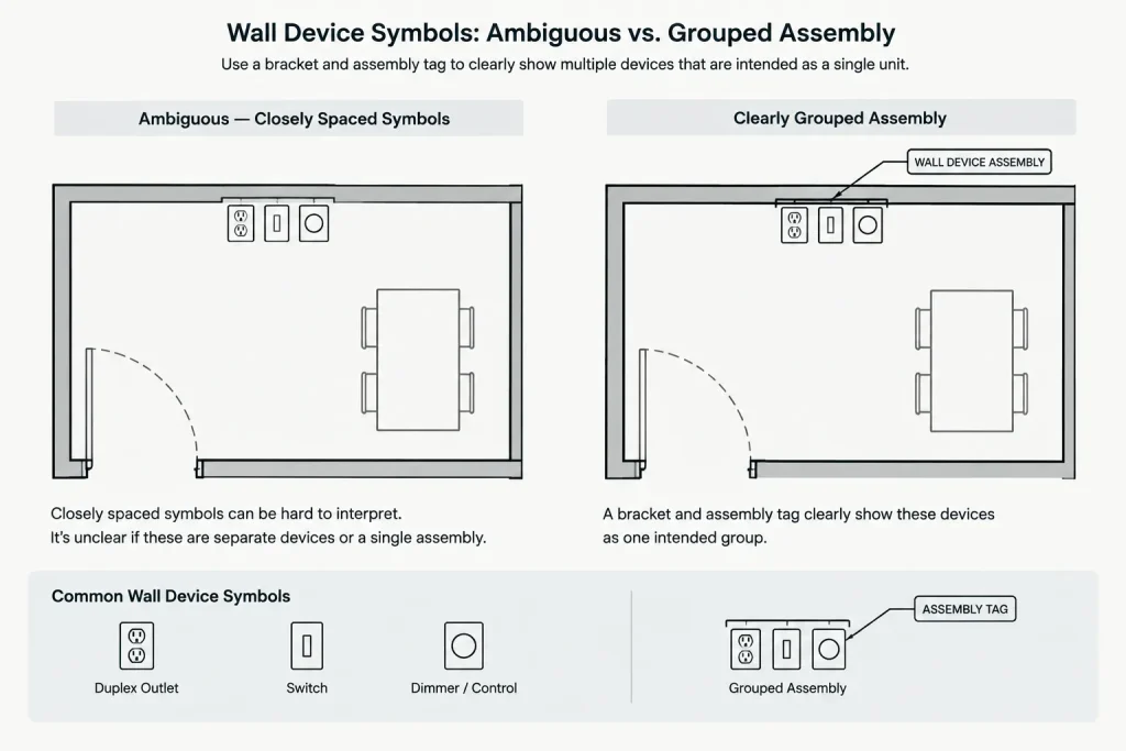
Electrical plan symbols are usually larger than the objects they represent so that they remain readable when plotted. When several symbols are placed around a doorway or workstation, their displayed spacing may bear little relationship to the actual spacing on the wall.
Common interpretation problems include:
- Symbols that appear grouped but were intended for separate wall locations
- Symbols that appear separate even though they belong in one coordinated assembly
- Overlapping tags that hide device types or circuit references
- Low-voltage devices shown without a clear scope designation
- Plan symbols that conflict with the corresponding interior elevation
- A combined symbol that conceals the individual devices included in the group
A consistent graphical convention is more reliable than relying on proximity alone.
Choose a Clear Plan-View Convention
There are several practical ways to show a grouped assembly. The best method depends on drawing scale, project complexity, and office standards.
Individual symbols with a grouping line
Place the required device symbols near the wall and use a short bracket, enclosure line, or other defined graphic to indicate association. This method preserves the identity of each device while showing that the devices belong together.
The grouping graphic should have one stated meaning. If a bracket means “coordinate at a common location,” it should not be used elsewhere to mean “common faceplate” unless the difference is explicitly noted.
Composite symbol with a device tag
A compact composite block can represent a recurring assembly, such as a standard workstation connection group or room control station. The block may carry an assembly tag linked to a legend, schedule, or detail.
This method reduces plan congestion, but it transfers important information away from the plan. The referenced description must identify the included components, and unusual exceptions should not be forced into a standard composite block.
Leader to an assembly note
For unique or crowded locations, a leader can point from the wall location to a short list of devices or to an assembly designation. This is useful when several discipline symbols would otherwise overlap.
Keep the leader target unambiguous. It should point to the intended location or grouping marker rather than to one device symbol if the note applies to the entire assembly.
Plan, Elevation, and Detail Roles
No single view needs to carry every piece of information. A coordinated drawing set assigns different responsibilities to the plan, elevation, detail, and schedule.
| Drawing element | Primary purpose | Typical information |
|---|---|---|
| Floor plan | Locate the assembly | Room, wall, device types, circuit or system association, assembly tag |
| Wall elevation | Show visible arrangement | Relative order, alignment, nearby casework, doors, finishes, and other wall-mounted items |
| Detail | Clarify a recurring condition | Grouping convention, interfaces, labeling approach, or verified mounting relationship |
| Schedule | Define assembly content | Included devices, service descriptions, responsibilities, and related references |
Use an elevation when horizontal or vertical arrangement affects coordination. A plan symbol may locate the group beside a door, but an elevation can reveal conflicts with trim, millwork, wall panels, signage, or architectural controls. The elevation should remain diagrammatic unless verified dimensions and installation requirements are available.
Build Reusable CAD Content Without Hiding Exceptions
A reusable assembly block can improve consistency, but it should not become a generic symbol that masks project differences. Start by separating stable graphics from variable information.

Stable content may include:
- A recognizable grouping boundary or bracket
- Standard device-symbol geometry
- A logical insertion point at the intended wall reference
- Consistent text locations and tag alignment
Variable content may include:
- Assembly identifier
- Device types included
- Circuit, panel, or system references
- Normal, backup, controlled, or other power designation
- Discipline responsibility
- Elevation or detail reference
Where the CAD workflow supports editable attributes, use them for data that changes by instance. Do not bury essential project information in a block name that is invisible on the plotted drawing. Block names are useful for library management, while visible tags and schedules communicate with drawing users.
Coordinate Power and Low-Voltage Scope
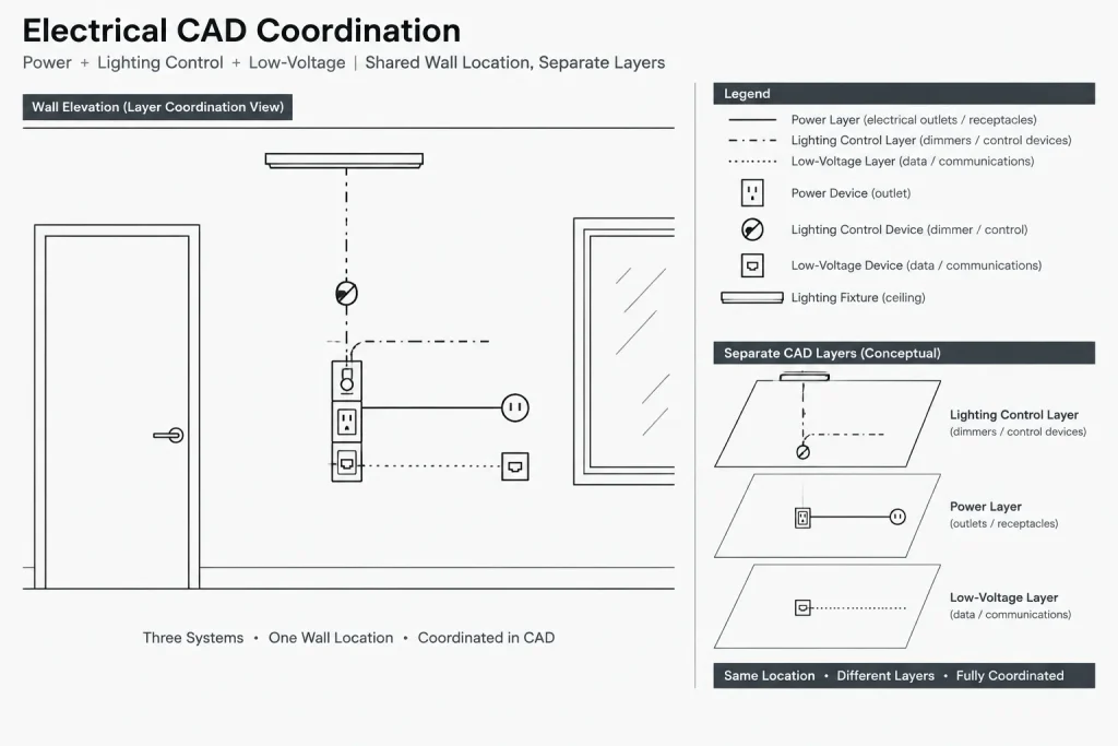
Grouped wall devices frequently cross discipline boundaries. A power receptacle may be documented by the electrical team, while data jacks, audiovisual connections, or control stations appear on separate drawings. Showing all devices for coordination can be valuable, but the graphics must not imply that one discipline is responsible for every item.
Useful scope methods include:
- Applying discipline-specific layers while retaining a common location reference
- Using a legend to identify reference-only or by-others symbols
- Assigning separate tags to devices while adding one shared assembly designation
- Cross-referencing the relevant technology, controls, or architectural drawing
- Using notes that define coordination responsibility without inventing installation requirements
Reference graphics should plot differently enough to indicate their status without becoming unreadable. Confirm that layer filtering and sheet production do not accidentally remove the context needed to understand the assembly.
Use Schedules for Repeated Assemblies
An assembly schedule is helpful when the same combination appears in many rooms. It can reduce repeated notes and make revisions easier to track. A practical schedule may contain an assembly tag, a plain-language description, the device symbols included, associated systems, and references to elevations or details.
Avoid treating the schedule as a substitute for location information. Every scheduled assembly still needs a clear plan location. Similarly, a plan tag should not point to a schedule entry that lists several optional combinations without identifying which combination applies.
Layer and Annotation Strategy
Keep device geometry, grouping graphics, tags, leaders, and reference information logically separated. This makes it easier to create discipline views, coordination plots, and presentation sheets without editing the underlying blocks.
A useful layer strategy distinguishes:
- Electrical power devices
- Lighting control devices
- Low-voltage or technology reference devices
- Assembly boundaries or grouping marks
- Device and assembly tags
- Elevation and detail references
Layer names should follow the project CAD standard rather than a newly invented convention. Check the final plotted output, because a grouping line that is obvious on screen may disappear when screened, reduced, or printed.
Quality-Control Checks
Before issuing the drawings, review multi-device assemblies as coordinated objects rather than isolated symbols.
- Confirm that every assembly tag has a matching legend or schedule entry.
- Compare plan device content with related elevations and details.
- Check both sides of walls to prevent unintended symbol stacking or conflicting locations.
- Review door swings, trim, casework, wall panels, and other architectural context.
- Confirm that circuit and system references belong to the correct device.
- Verify that mirrored rooms preserve intended device order and access relationships.
- Look for blocks copied from earlier areas with outdated attributes.
- Plot at the intended sheet scale and check symbol, tag, and leader readability.
- Confirm that reference-only devices remain identifiable when discipline layers are filtered.
Automated block counts can help find missing or duplicated content, but they cannot determine whether nearby devices were meant to form one physical assembly. Visual review remains essential.
A Practical Documentation Workflow
Begin by identifying recurring device combinations from the project plans and room requirements. Decide whether each combination needs individual symbols, a composite symbol, or an assembly tag. Establish one clear graphical convention and explain it in the legend or notes.
Place assemblies using a repeatable wall-relative insertion point. Add instance-specific tags and system information, then coordinate the locations with architectural backgrounds and other discipline drawings. Create elevations for congested or arrangement-sensitive conditions. Finally, reconcile plans, schedules, elevations, and details before plotting.
Well-documented multi-device wall assemblies make electrical CAD plans easier to interpret without pretending that the plan symbol is a fabrication drawing. Clear grouping, visible device identity, disciplined cross-references, and coordinated elevations allow the drawing set to communicate intent while leaving unverified physical construction details for appropriate project review.
How to Select the Right Grouping Method
Choose the representation according to what the drawing user must understand. Individual symbols with a grouping mark are useful when device identity must remain visible. A composite block is more effective for a recurring, well-defined combination. An assembly tag with a leader can clarify a crowded or unique location without compressing several symbols into an unreadable cluster.
Before selecting a method, ask what the graphic is intended to confirm: a common wall area, a coordinated visible arrangement, or a verified shared assembly. Those meanings are not interchangeable. If the available project information confirms only a common location, the drawing should not imply a common enclosure or faceplate.
Apply an Ambiguity Test
A useful quality check is to review the plan without relying on personal knowledge of the project. A reader should be able to determine:
- Which devices belong to the same coordinated location
- Which symbols identify power, lighting control, and low-voltage functions
- Whether a device is part of the documenting discipline’s scope or shown for reference
- Where the assembly definition or additional arrangement information is located
- Whether the grouping indicates association only or a verified physical relationship
If the answers depend only on symbol proximity, color, or an unpublished office convention, the documentation needs a clearer grouping mark, tag, legend note, schedule entry, or cross-reference.
Protect Assembly Data During Revisions
Grouped devices are especially vulnerable to partial revisions. A drafter may update the plan symbol while leaving the schedule, elevation, or referenced discipline drawing unchanged. Treat the assembly designation as a coordinated data point and review every location where it appears.
When copying an assembly, retain only information that remains valid at the new location. Room-specific circuit references, system identifiers, scope notes, and elevation references should be checked rather than inherited automatically. If the device combination changes, decide whether the existing assembly definition should be revised globally or whether the location requires a distinct designation.
Keep the Graphic Meaning Stable
The same bracket, boundary, line style, or composite symbol should have the same meaning throughout the drawing set. Changing its interpretation from one sheet to another forces readers to infer intent and can create coordination errors. Record the convention in the symbol legend, general notes, or assembly schedule, using the documentation location that is easiest for drawing users to find.
Final review should include both the editable CAD view and the plotted sheet. Layer states, screening, clipping, and annotation placement can change how the grouping reads even when the underlying model is correct.
Frequently Asked Questions
Does graphical grouping mean the devices share one faceplate?
No. Graphical grouping may indicate only that devices occupy the same general wall location. A shared faceplate, enclosure, or mounting arrangement should be shown only when supported by verified project information.
When should individual device symbols be used instead of a composite block?
Use individual symbols when each device must remain immediately identifiable on the plan or when the combination varies by location. A composite block is better suited to a recurring assembly that has a clear tag, definition, and method for documenting exceptions.
How should low-voltage devices appear beside power devices?
They may be shown together for coordination while remaining separated by layers, tags, symbol conventions, or scope notes. The drawing should make clear which discipline documents each device and where its detailed information can be found.
When is a wall elevation helpful?
A wall elevation is helpful when device order, alignment, nearby doors, casework, finishes, controls, or other wall-mounted elements affect coordination. It supplements the plan location without requiring the plan symbol to depict the complete visible arrangement.
Can an assembly schedule replace device symbols on the plan?
A schedule can define the contents of a repeated assembly, but the plan still needs an unambiguous location and tag. The schedule and plan should work together rather than requiring readers to guess which combination applies.
How should mirrored rooms be checked?
Review the device sequence and surrounding architectural context instead of mirroring graphics without verification. A geometrically mirrored block may not preserve the intended relationship to doors, casework, controls, or user access.












Leave a Reply
You must be logged in to post a comment.