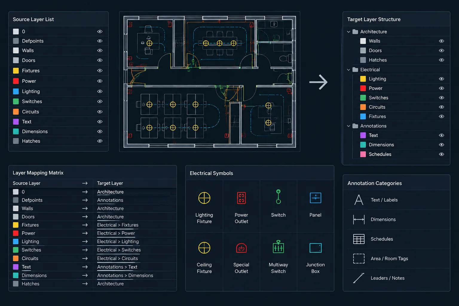
Translating an electrical drawing into a client or consultant layer standard requires more than matching names. Each source layer may carry information about object function, work status, annotation, visibility, plotting, or ownership. If those relationships are overlooked, a drawing can appear organized while becoming less useful for coordination and revision.
This guide presents a controlled approach to electrical CAD layer mapping. It focuses on classifying content, documenting translation decisions, handling blocks and references, isolating uncertain objects, and validating the converted drawing against its source.
Electrical CAD files often move between organizations that use different layer names, colors, linetypes, plot conventions, and discipline prefixes. A lighting layer in one office may be divided into fixture, circuiting, control, and annotation layers in another. Simply renaming everything to match a target template can erase useful distinctions, disrupt plotting, or make future coordination difficult.
Electrical CAD layer mapping is the controlled process of translating source layers into a project’s required layer structure. The objective is not merely to make the layer list look familiar. A successful mapping preserves drawing meaning, maintains visual hierarchy, supports editing, and provides a record of how the source information was handled.
When Layer Mapping Is Useful
Layer mapping commonly becomes necessary when incorporating consultant backgrounds, owner-provided record drawings, vendor layouts, legacy details, or files created under a different CAD standard. It may also be part of a formal deliverable requirement when the recipient expects specific layer names and property conventions.
Not every incoming file needs to be converted. An architectural background used only as an external reference can often remain in its source structure, with its display controlled in the host drawing. Conversion is more appropriate when electrical content must become editable project geometry, when files are being consolidated, or when the final deliverable must follow a defined layer standard.
Begin With an Inventory, Not a Rename Command
Before changing layers, inspect the source file and identify what each layer actually contains. Names can be misleading. A layer labeled for power may contain receptacles, equipment connections, circuit lines, text, and demolition notes. Mapping that entire layer to a single target layer would preserve the name category while losing important separation.
A useful inventory should consider:
- Layer name and apparent purpose
- Object types found on the layer
- Color, linetype, lineweight, and transparency behavior
- Whether properties are controlled by layer or overridden on individual objects
- Whether the content is existing, new, demolished, future, or informational
- Whether the layer appears inside blocks or external references
- Whether it contains model geometry, annotation, dimensions, hatches, or viewport-related content
Open representative areas of the drawing rather than relying entirely on the layer list. A layer with only a few objects may still contain critical tags or continuation graphics.
Create a Source-to-Target Mapping Table
A mapping table turns an informal cleanup task into a reviewable documentation process. It can be maintained in a worksheet, project note, or controlled CAD standard document. The table should identify the source layer, intended target, treatment, and any concerns requiring verification.
| Source content | Target treatment | Review concern |
|---|---|---|
| Lighting fixture symbols | Map to the project fixture layer | Confirm emergency or special fixture distinctions are retained |
| Lighting circuit lines | Map to the project circuiting layer | Check linetype visibility and routing readability |
| Device tags and identifiers | Map to an electrical annotation layer | Verify text remains associated with the correct device |
| Demolition graphics | Map to the applicable demolition layer group | Do not merge with new-work geometry |
| Unclassified source objects | Place on a temporary review layer | Resolve before final issue or delivery |
A many-to-one mapping may be acceptable when several source layers truly represent the same drawing function. A one-to-many conversion requires more care because objects must be separated by meaning, not merely renamed as a group.
Map by Drawing Function
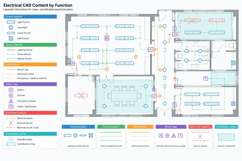
The most reliable target layer is determined by what an object communicates. A fixture symbol, its identification tag, its circuiting line, and its control relationship may appear visually related, but they serve different documentation functions. Keeping them separate improves plotting, selective visibility, scheduling, and revision work.
Useful functional categories include:
- Equipment and device symbols
- Branch circuit or feeder linework
- Control relationships
- Text, tags, and keynotes
- Existing and demolition content
- Clearance, access, or coordination zones
- Detail, section, and elevation graphics
- Non-plot construction or drafting aids
The exact names should follow the project’s approved convention. The functional distinction matters more than copying a layer name from an unrelated template.
Handle Blocks and Nested Objects Carefully
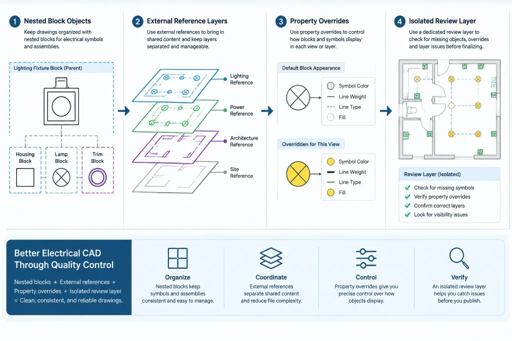
Blocks can hide layer conditions that are not obvious in plan view. A block reference may be inserted on an electrical fixture layer while lines, text, wipeouts, or attributes inside the definition remain on source-specific layers. Renaming only the insertion layer does not necessarily complete the translation.
Inspect representative block definitions and determine whether internal objects intentionally inherit the insertion layer’s properties or require dedicated target layers. Avoid flattening all nested content onto one layer without understanding the consequences. Doing so can prevent portions of a symbol from responding correctly to layer visibility and plotting controls.
Dynamic behavior, attributes, and visibility configurations should also be checked after conversion. If a block must be rebuilt, preserve a copy of the source definition until the replacement has been reviewed in every relevant view.
Separate External References From Imported Content
External references and native drawing objects require different strategies. Renaming layers in a referenced consultant file can complicate future updates because a newly received background may restore the original layer structure. It can also make the project team responsible for maintaining a file that belongs to another discipline.
For referenced backgrounds, consider controlling appearance through host-drawing visibility and display settings rather than modifying the source. If the file must be edited or incorporated permanently, document the point at which it became project-owned content and apply the mapping to a controlled copy.
Before binding, importing, or otherwise converting reference content, evaluate how layer names may be prefixed or combined. Test the process in a duplicate file so that the production drawing remains recoverable.
Preserve Status and Phase Information
One of the most damaging mapping errors is merging different work statuses. Existing equipment, demolition, relocation, new work, and future provisions may use similar symbols but communicate different scope. If those distinctions are encoded in layers, they must survive the translation.
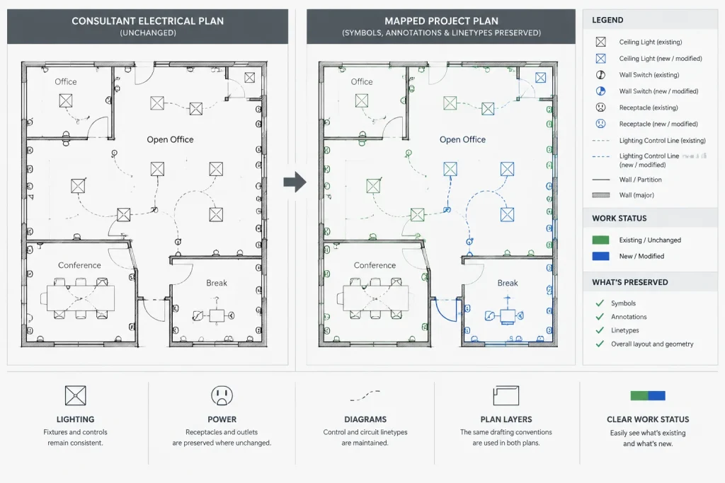
Do not assume that color alone represents status. Color may be controlled by a plot style, used for screen organization, or overridden on selected objects. Review linetypes, notes, symbols, and sheet context before deciding how status information should map.
Use a Quarantine Layer for Unresolved Objects
Ambiguous objects should not be forced into the nearest available layer simply to complete the conversion. A clearly named temporary review layer provides a controlled place for uncertain content. This layer should be visually distinctive during coordination and excluded from final plotting only after its contents have been resolved.
Examples include unidentified linework, anonymous block fragments, abandoned revision graphics, duplicate symbols, and text with no apparent drawing relationship. Record the reason for uncertainty so another reviewer can make an informed decision.
Validate the Drawing After Translation
A technically completed layer conversion can still produce a poor drawing. Validation should include both data checks and visual review.
Visual review
- Compare the converted drawing with an unchanged source copy.
- Check representative lighting, power, equipment, and annotation areas.
- Confirm dashed or hidden linework remains visible at plotted scale.
- Look for missing text, solid-filled symbols, unexpected screening, and altered draw order.
- Review demolition and existing-work graphics separately from new work.
Layer and object review
- Search for objects left on obsolete source layers.
- Inspect objects carrying individual property overrides.
- Review nested layers within frequently used blocks.
- Confirm required non-plot layers do not print.
- Check that target layers are not empty duplicates created by spelling or naming variations.
Coordination review
- Reload relevant backgrounds and confirm alignment has not changed.
- Verify device tags still correspond to symbols and schedules.
- Confirm circuiting, home runs, and continuation graphics remain connected visually.
- Review sheets and viewports rather than checking model space alone.
Maintain an Audit Trail
Save the mapping table with the project’s CAD documentation, especially when translated files will be updated later. Note the source file, conversion purpose, unresolved exceptions, and review status. If revised consultant files arrive, the established mapping can be repeated consistently instead of being reconstructed from memory.
For recurring exchanges, maintain a reusable mapping profile while still reviewing every incoming file. Two files from the same organization may use similar layer names but contain different object types or project-specific exceptions.
A Practical Layer Mapping Sequence
-
Work from a controlled copy of the source drawing.
-
Review layer names, properties, object types, blocks, references, and work-status conventions.
-
Prepare a source-to-target mapping table based on drawing function.
-
Resolve obvious mappings first and isolate uncertain content for review.
-
Translate native objects while treating external references separately.
-
Inspect blocks, nested objects, annotations, and property overrides.
-
Compare the result with the unchanged source in model and sheet views.
-
Remove obsolete layers only after confirming they contain no required information.
-
Record exceptions and retain the mapping documentation for future updates.
Layer Mapping Is an Information Task
Electrical CAD layer mapping should be treated as information translation rather than cosmetic cleanup. The best result is not necessarily the drawing with the shortest layer list. It is the drawing in which symbols, circuiting, annotations, status graphics, and coordination information remain understandable under the target project standard.
A documented, function-based process reduces accidental data loss and makes later updates easier to manage. It also gives reviewers confidence that the converted drawing still communicates the same electrical intent as the source, subject to normal project verification.
Define Acceptance Criteria Before Mapping
A layer translation is easier to review when the project team agrees on what the converted file must preserve. Acceptance should be based on drawing behavior and information quality rather than layer names alone.
Useful acceptance criteria may include:
- Electrical symbols remain distinguishable by drawing function.
- Annotations stay associated with the correct devices and linework.
- Existing, demolition, new-work, and other status distinctions remain understandable.
- Required objects respond correctly to target-layer visibility controls.
- Plot appearance retains the intended hierarchy without hiding important content.
- Blocks, attributes, hatches, and nested objects behave as expected.
- Unresolved objects are documented instead of silently discarded.
Evaluate Mapping Risk by Information Loss
Not every mapping decision carries the same risk. Combining layers that contain equivalent drafting content may have little effect, while combining geometry and annotation or merging different work statuses can change how the drawing is interpreted.
Higher-risk decisions deserve focused review. These include one-to-many translations, layers containing mixed object types, content with individual property overrides, nested block geometry, and objects whose meaning depends on a plot style or viewport setting. Flagging these conditions in the mapping record helps reviewers concentrate on changes most likely to affect documentation.
Test the Target Workflow, Not Just the Converted File
A successful result should work in the recipient’s normal documentation environment. Apply expected visibility controls, open representative sheets, inspect plotted output, and test common editing tasks. This can reveal issues that are not apparent from a layer list, such as annotations disappearing with geometry, symbol components plotting inconsistently, or background layers overwhelming electrical information.
The final review should also confirm that future updates remain manageable. Preserve the unchanged source, the approved mapping record, and notes explaining exceptions. These materials make it easier to repeat the translation without relying on undocumented judgment.
Frequently Asked Questions
Is layer mapping the same as renaming layers?
No. Renaming changes identifiers, while mapping evaluates what the objects communicate and assigns them to suitable target layers. Mapping may also require separating mixed content, reviewing nested objects, and preserving status or plotting behavior.
Should every consultant layer be converted?
Not necessarily. A referenced background may remain in its original structure when it does not need to become editable project content. Conversion is more relevant when objects are incorporated into the project drawing or the deliverable must follow a defined target convention.
Can layer color be used to determine an object’s purpose?
Color can provide context, but it should not be treated as conclusive evidence. Its meaning may depend on plot settings, office practices, viewport controls, or object-level overrides. Review symbols, linetypes, notes, and drawing context before assigning a target.
What should happen to an object with no clear target layer?
Place it on a controlled review layer and document why it is unresolved. Keeping ambiguous content visible for review is safer than forcing it into an inaccurate category or deleting it without confirmation.
How can a reviewer tell whether a layer conversion is complete?
Completion requires more than an empty list of source layers. Compare the result with the unchanged file, inspect blocks and overrides, review model and sheet views, verify plot behavior, and confirm that annotations, circuiting, status graphics, and references still communicate the intended relationships.
Does matching the client’s layer names prove that the file complies with the client’s CAD requirements?
No. Names are only one part of a CAD convention. Object placement, property control, plotting, reference handling, block construction, and documentation requirements may also need review against the project’s approved instructions.












Leave a Reply
You must be logged in to post a comment.