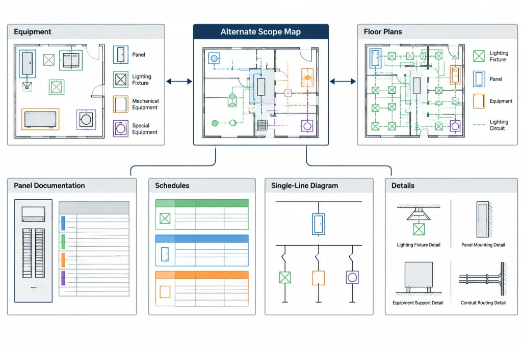
Electrical alternates in CAD must communicate more than optional geometry. They must show what belongs to the base scope, what changes when a bid option is accepted, and which plans, schedules, diagrams, details, and demolition documents are affected.
This reference explains how to organize that information so the plotted drawing set remains understandable without access to native layer controls. It focuses on scope mapping, visible identifiers, coordinated references, alternate combinations, and drawing quality control.
Electrical alternates can affect equipment, feeders, branch circuits, lighting, controls, pathways, and demolition work across an entire drawing set. If an alternate is identified only by a note on one floor plan, bidders and reviewers may not recognize its effects elsewhere. If alternate geometry is simply placed on a hidden CAD layer, it may disappear from plots or remain visible on sheets where it does not apply.
A reliable workflow treats each alternate as a coordinated scope package rather than a collection of isolated annotations. The objective is to let a reader distinguish the base design from each optional condition and trace that distinction through plans, schedules, diagrams, and details. Contract terminology and procurement requirements vary, so the project team should verify how alternates are defined and presented before establishing the CAD approach.
Start with a written scope map
Before editing drawings, create a scope map for every alternate. This can be a simple working table maintained outside the issued sheets or included in a drawing coordination log. It should state what changes, what remains part of the base scope, and which drawings may be affected.
| Coordination item | Questions to resolve |
|---|---|
| Equipment | Is equipment added, deleted, replaced, relocated, or resized? |
| Distribution | Are sources, panel assignments, feeders, disconnects, or protective-device references affected? |
| Branch systems | Do device quantities, circuit routes, home runs, or control relationships change? |
| Pathways | Are raceways, cable trays, sleeves, boxes, or reserved routes included? |
| Schedules | Which fixture, equipment, panel, feeder, cable, or connection entries require alternate notation? |
| Details | Does the option require a different installation concept, mounting arrangement, or interface detail? |
| Other disciplines | Do architectural, structural, mechanical, civil, or technology documents show related optional work? |
This exercise exposes secondary effects early. An optional piece of equipment, for example, may also affect its plan symbol, connection tag, equipment schedule, distribution diagram, pathway route, and associated notes.
Choose a consistent graphic strategy
There is no universal graphic method for every project. The best approach depends on the complexity of the alternate and the organization of the drawing set. Whichever method is selected should be explained in the legend or drawing notes and applied consistently.
Keyed alternate notes
Keyed notes work well when an alternate modifies a limited number of clearly defined locations. Place the note marker close to the affected object and write the note so it identifies both the optional work and the base condition when necessary.
Avoid vague wording such as “alternate work here.” A useful note describes the drawing consequence: provide an optional device, omit a base item, use a different connection, or extend a pathway only when the alternate is accepted. The final language should match the project team’s procurement terminology.
Boundaries and scope clouds
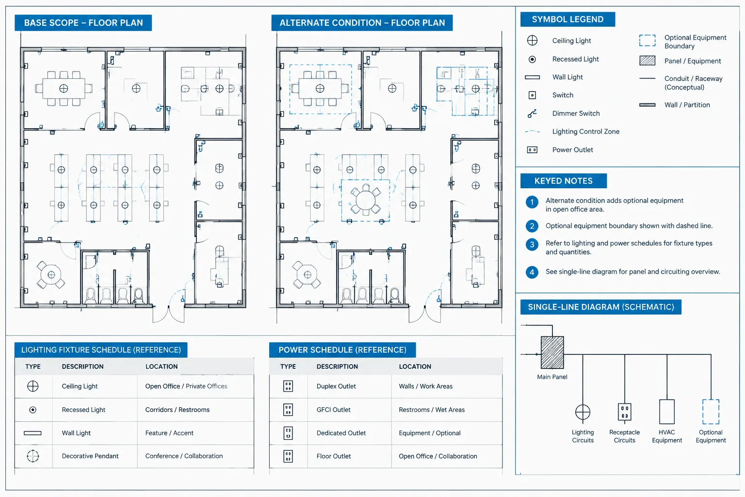
A labeled boundary can communicate an optional area, room, site zone, or group of devices. Use a visually distinct but controlled linetype or hatch that remains readable over the background. The boundary should not conceal circuiting, dimensions, room names, or equipment tags.
Scope clouds should not be confused with revision clouds. If similar graphics are used for both purposes, readers may interpret an alternate boundary as a post-issue change. A dedicated boundary style and direct label reduce that risk.
Separate alternate views or sheets
When an alternate substantially changes a plan, a separate view or sheet is often clearer than overlapping two designs. This is particularly useful when equipment arrangements, circuiting, or pathway routes differ enough that both conditions cannot be read together.
The alternate view should state what it replaces. A caption such as “alternate condition; replaces corresponding base-scope area when accepted” communicates the relationship more clearly than presenting a second plan without context.
Use CAD layers as controls, not as the only explanation
Layers can separate base-scope geometry from optional work, but layer names alone are not contract communication. Most drawing users review plotted sheets or PDFs rather than the native CAD layer structure.
A practical layer arrangement may distinguish:
- Base electrical objects
- Alternate-specific objects
- Alternate boundaries and labels
- Optional demolition or removal
- Alternate annotations and references
Include an alternate identifier in each relevant layer name according to the project’s naming convention. Do not place every alternate on one generic layer if the project contains several independent options. Separate controls make it easier to review combinations and prevent one option from being plotted accidentally with another.
Test sheet viewports and plotting states after changing layers. An alternate may appear correctly in model space while being frozen in a viewport, screened by a plot setting, or visible on a sheet intended to show only the base scope.
Coordinate plans with schedules and diagrams
Plan graphics are only one part of the documentation. Every alternate should be traced through the other representations of the affected system.
Equipment and fixture schedules
Do not rely on color alone to identify optional schedule entries. Add a written alternate designation in a dedicated status field, remarks column, description, or related note. If the alternate changes a scheduled characteristic, make the base and optional conditions distinguishable without forcing the reader to compare ambiguous duplicate rows.

Panel and circuit documentation
An optional load may affect panel descriptions, circuit identifiers, connection references, and load documentation. Coordinate these items with the project’s engineering calculations rather than inferring values in CAD. Clearly distinguish reserved positions, future provisions, base-scope circuits, and alternate circuits because those terms do not necessarily mean the same thing.
Single-line and riser diagrams
Show how the alternate affects the distribution path, not merely where optional equipment sits on a floor plan. Use a labeled boundary, note, or separate diagram segment to identify optional sources, feeders, devices, and loads. Check that identifiers agree with plans and schedules.
Details and sections
If a detail applies only to an alternate, say so in the detail title or adjacent note. If a common detail applies to both conditions, avoid duplicating it unless the duplicate provides genuine clarity. References from the plan should lead to the correct detail for the applicable scope.
Show base scope without creating contradictions
An alternate is easier to understand when the reader knows what happens if it is not accepted. Depending on the project, the base condition may remain unchanged, receive different equipment, include a capped provision, or omit the work entirely. The drawings should not leave that condition to guesswork.
Common documentation problems include:
- An alternate plan adds equipment without showing whether base equipment remains.
- A schedule lists both base and optional items as if both will be installed.
- A single-line diagram includes an optional feeder with no alternate label.
- Demolition associated with an alternate appears on the base demolition plan.
- An optional device is tagged to a base-scope circuit with no explanation.
- Architectural and electrical drawings use different alternate names.
Resolve these conflicts with explicit status notes and consistent identifiers rather than relying on dashed lines whose meaning may vary from sheet to sheet.
Handle demolition and renovation alternates separately
Renovation work often requires two decisions: whether existing construction is removed and whether new work is installed. Those decisions should not be combined into one ambiguous symbol.
Where appropriate, distinguish optional demolition from optional new work with separate layers and notes. Confirm that accepting or rejecting the alternate does not leave unexplained gaps between demolition and construction sheets. Existing-to-remain objects should remain identifiable even when optional work is turned on for review.

Review alternate combinations
Some alternates are independent; others are mutually exclusive, cumulative, or dependent on another option. The drawings should not silently assume that all alternate layers will be enabled together.
Create review plots for each permitted condition:
- Base scope only
- Each alternate shown individually
- Allowed combinations of alternates
- Any condition in which one alternate replaces another
During review, look for duplicate symbols, overlapping tags, conflicting circuit references, disconnected diagram elements, and notes that become inaccurate when a different combination is displayed.
Keep identifiers stable through revisions
Once alternate identifiers are used in issued documents, avoid casually renaming or renumbering them. A change can affect notes, schedule remarks, diagram labels, specifications, cost documents, and review comments.
If the scope changes, record the change through the project’s revision process. Review whether earlier alternate graphics must be removed, revised, or reclassified as base scope. Revision marks should identify the current drawing change without replacing the permanent alternate designation.
CAD quality-control checklist
- Confirm that every alternate has a unique, consistently written identifier.
- Verify that base scope remains understandable when alternate layers are off.
- Check plans, diagrams, schedules, details, and demolition sheets for related scope.
- Confirm that alternate boundaries are not mistaken for revision clouds.
- Review viewport-specific layer settings and final plots.
- Search drawing text for obsolete alternate names.
- Check that tags and cross-references lead to the correct schedules and details.
- Compare alternate terminology with other disciplines and project documents.
- Review each allowed alternate combination rather than only the fully layered model.
- Verify engineering values and project requirements with the responsible design team.
Build the drawings around decisions
Clear alternate documentation helps readers answer three questions: What is included in the base design? What changes if the option is accepted? Where else is that change documented? CAD layers, blocks, and view controls support those answers, but they cannot replace visible labels and coordinated references.
By mapping the scope first, selecting a consistent graphic method, and reviewing every affected drawing type, the drafting team can present electrical alternates as understandable design choices instead of hidden layer combinations. The result is a drawing set that is easier to price, review, revise, and coordinate.
Maintain an alternate decision record
Drawing coordination continues after the first alternate graphics are created. Maintain a decision record that connects each alternate identifier to its current status, affected sheets, related schedule entries, diagram references, and coordination responsibilities. This record can help the team determine whether a later change modifies the option, transfers work into the base scope, or removes the option from the documents.
The record should support the drawings rather than introduce a separate definition of scope. When its wording conflicts with an issued note, schedule, specification, or procurement document, the project team should resolve the discrepancy through its established review process.
Separate authoring controls from reader communication
CAD layers, filters, view states, and block visibility settings are authoring tools. Alternate labels, notes, boundaries, captions, and cross-references are reader communication. A dependable workflow uses both: authoring controls manage the file, while visible annotations explain the plotted result.
This distinction is especially important when drawings are exported, combined, printed in grayscale, or reviewed outside the original CAD platform. The meaning of an alternate should survive those transitions without depending on color, layer names, or interactive visibility settings.
Check the issue package as a complete system
Before issue, review the assembled package rather than checking each sheet only in isolation. Follow an affected item from its plan location to its tag, schedule entry, circuit or connection reference, diagram representation, detail callout, and related demolition note. The same alternate identifier and scope relationship should remain clear at every step.
Also review sheet titles, legends, general notes, and drawing indexes where applicable. These locations can unintentionally imply that an alternate view is part of the base design or that an optional sheet applies unconditionally.
Preserve clarity after an alternate decision
Acceptance or rejection of an alternate does not automatically make the existing CAD presentation suitable for later project phases. The team should determine whether optional graphics remain labeled as historical bid information, are incorporated into the active design, or are removed under the project documentation procedure.
Avoid merely turning layers on or off without reviewing references elsewhere. Notes, schedules, diagram branches, detail titles, and demolition graphics may continue to describe the earlier condition even when the plan appears correct.
Frequently asked questions
What is an electrical alternate on a drawing set?
An electrical alternate is an identified option that changes defined work relative to the base scope. It may affect equipment, distribution, lighting, controls, pathways, demolition, schedules, diagrams, or related details.
Can alternate work be documented only with CAD layers?
No. Layers can control authoring and visibility, but plotted documents should include readable labels, notes, boundaries, captions, or references that explain the optional condition.
How should base scope be shown beside an alternate?
The drawings should state what remains, what is omitted, and what is replaced when the option is accepted. The exact presentation may use keyed notes, separate views, labeled boundaries, schedule remarks, or coordinated diagram annotations.
Should alternate boundaries look like revision clouds?
They should be visually distinguishable. Similar graphics can cause readers to mistake optional scope for a drawing revision, so direct labels and a dedicated graphic convention are helpful.
When is a separate alternate view preferable?
A separate view is useful when overlapping conditions would obscure equipment, circuiting, pathways, tags, or annotations. Its caption should identify the applicable option and explain its relationship to the corresponding base condition.
How should optional schedule entries be identified?
Use written alternate designations in an appropriate field, description, remark, or note. Do not depend on color alone, and make sure the schedule terminology matches the plans and diagrams.
What should be reviewed before issuing alternate drawings?
Review base-only plots, applicable option conditions, permitted combinations, viewport visibility, cross-references, schedules, diagrams, details, demolition work, and terminology used by other disciplines.












Leave a Reply
You must be logged in to post a comment.