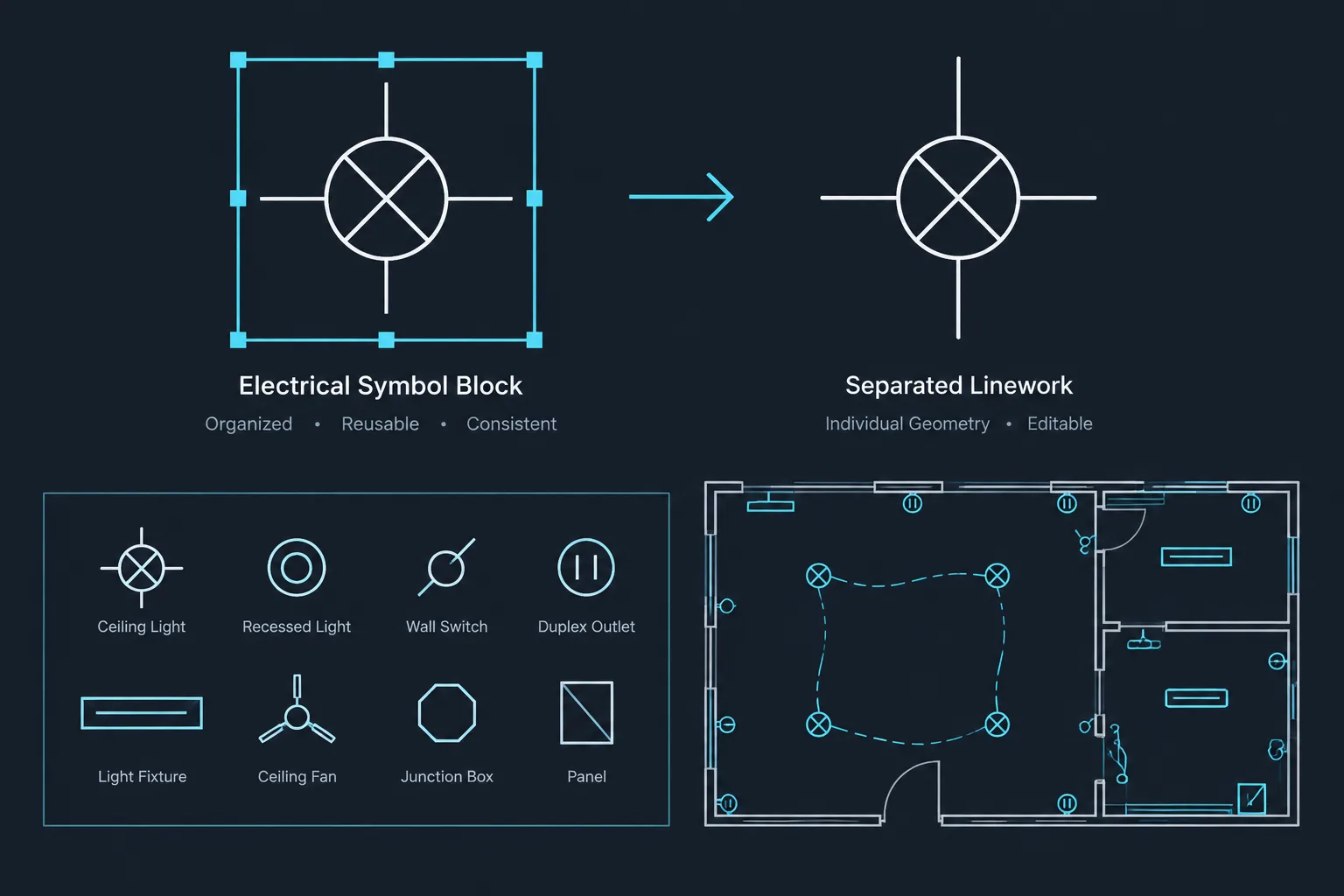
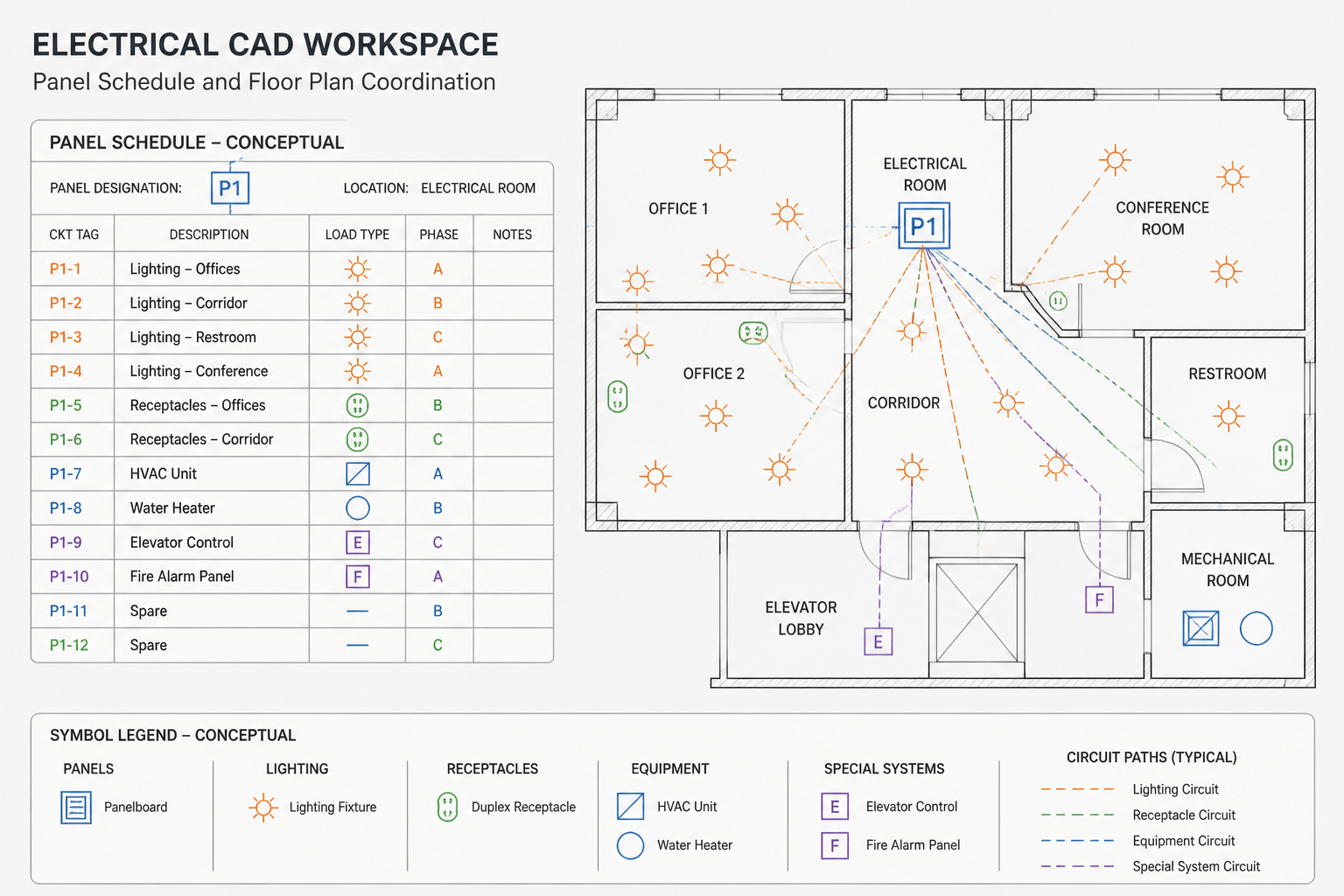
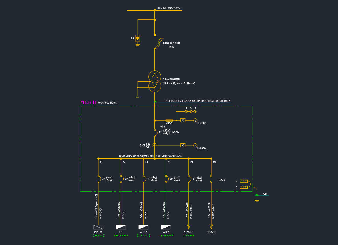
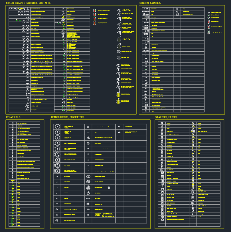
Electrical symbols often carry more information than their visible linework suggests. Before exploding a block to make a quick graphic change, a drafter should determine whether the object also controls attributes, repeated instances, layer behavior, schedules, or project-wide consistency.
This reference compares the main editing choices and explains how to protect the documentation value of a symbol. The central question is not simply whether a block can be exploded, but whether its identity and behavior must remain available after the edit.
Exploding an electrical CAD block may seem like the fastest way to change a symbol, but it can also remove the structure that makes the object useful. A receptacle symbol can become a collection of unrelated lines, an equipment block can lose editable attributes, and identical devices can quietly develop different graphics across the same drawing set.
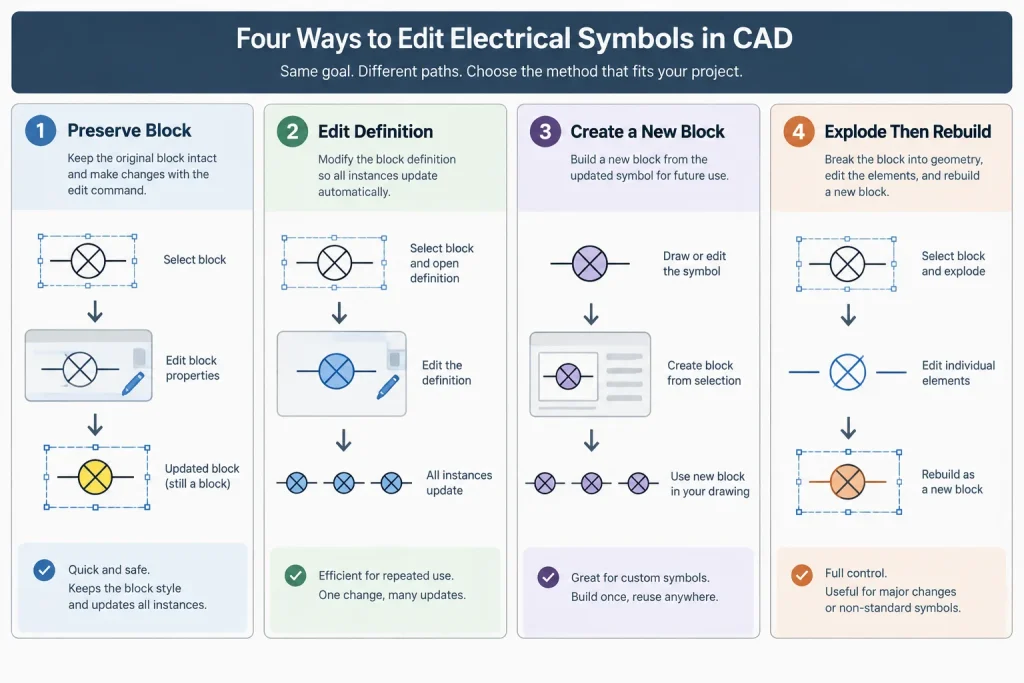
A practical block-editing workflow starts by identifying what the block contains and why it was created. Some blocks are simple reusable graphics. Others carry tags, visibility options, nested symbols, annotation behavior, or data used in schedules. The correct choice may be to preserve the block, edit its definition, create a project-specific copy, or rebuild it from clean geometry. Exploding should be a controlled decision rather than a default editing method.
What Happens When a CAD Block Is Exploded?
A block groups multiple objects under one definition and provides a consistent insertion point, name, orientation, and graphic identity. When it is exploded, the grouped object is converted into its component geometry and text. Depending on how the block was constructed, this can affect more than its appearance.
Potential consequences include:
- The object is no longer counted as an instance of the original block.
- Attribute data may be converted, separated, or lost from the intended workflow.
- Nested blocks may remain nested or may require additional processing.
- Objects may revert to their internal layers, colors, linetypes, or lineweights.
- Configurable parameters and visibility choices may no longer be available.
- Future edits to the original block definition will not update the exploded copy.
- The resulting geometry may be harder to select, move, rotate, audit, or replace.
The visual result can look correct while the underlying documentation becomes less reliable. This is especially important when block names or attributes are used for device counts, equipment lists, drawing comparisons, or automated checks.
Four Editing Choices
Before exploding a symbol, decide which of the following approaches best matches the intended change.
| Approach | Best used when | Main concern |
|---|---|---|
| Preserve the block | The symbol is correct and only its location, rotation, scale, layer, or attributes need adjustment | Avoid unnecessary changes to shared definitions |
| Edit the definition | Every instance of the block should receive the same correction | Confirm that a global update is intended |
| Create a new block | The revised symbol represents a distinct device, status, view, or project condition | Use a clear name and prevent near-duplicate blocks |
| Explode and rebuild | The source block is damaged, poorly structured, incompatible with the library, or needed only as reference geometry | Reconstruct layers, attributes, insertion point, and graphic behavior deliberately |
When the Block Should Usually Be Preserved
The change affects only one insertion
Moving a device, rotating a symbol, changing an attribute value, or selecting a different configured state does not normally require an explosion. These are insertion-level changes and should remain separate from the block definition whenever possible.
The block participates in schedules or counts
If a block name or attribute is used to identify devices, exploding it can remove it from quantity checks and data-extraction workflows. A symbol that looks like a fixture but is no longer recognized as the fixture block may cause discrepancies between plans and schedules.
The symbol appears throughout the project
Shared symbols benefit from centralized control. Correcting the definition allows all valid instances to remain coordinated. Editing separate exploded copies creates multiple versions that can no longer be updated together.
The block contains nested content
Equipment assemblies may contain nested connection points, labels, clearance graphics, or separate plan and annotation components. Review the hierarchy before changing it. An apparently simple block may support several documentation tasks.
When Editing the Definition Is Better
Edit the block definition when the current graphic is wrong in the same way everywhere. Examples include correcting an unintended line, moving a consistent text placeholder, assigning internal objects to the proper layer strategy, or improving the symbol’s base geometry.
Before making a definition-wide edit:
- Identify every drawing area where the block is used.
- Check whether the same name represents more than one graphic in imported files.
- Review nested blocks and attribute locations.
- Confirm the insertion point will remain stable.
- Test rotations, mirrored placements, and plotted output.
- Save a controlled backup or work in a review copy.
Changing the insertion point deserves particular care. Existing instances may appear to shift if the definition is rebuilt around a different base location. If a new insertion behavior is required, creating a new block may be safer than altering a widely used one.
When to Create a Project-Specific Copy
A new block is appropriate when the revised object has a meaning different from the library original. For example, an existing device, a new device, and a device to be removed may need related graphics but different status controls. Similarly, an equipment symbol with a special connection arrangement should not necessarily overwrite the generic equipment block.
Give the new block a name that communicates its purpose without embedding temporary notes or personal initials. Document the distinction in the symbol legend or project CAD notes when users could reasonably confuse the two versions.
A project-specific copy should still follow the project’s conventions for layers, attributes, text, insertion points, and plotting. Copying a library block is not a reason to abandon library discipline.

When Exploding Can Be Reasonable
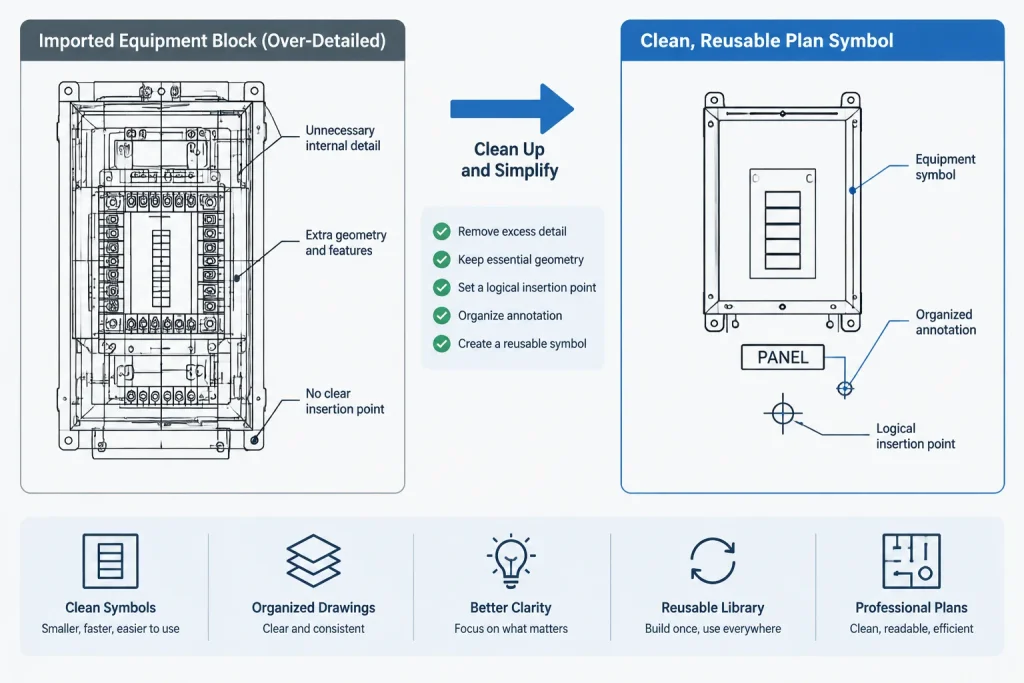
Exploding can be useful as an intermediate cleanup step when a received block is unsuitable for continued use. Common examples include imported vendor graphics with excessive detail, anonymous or unidentifiable blocks, corrupted definitions, symbols containing irrelevant geometry, or objects that must be simplified before being rebuilt.
In these cases, place the source object in a controlled working area or separate file. Explode it there, retain only necessary drafting geometry, and construct a new block rather than leaving loose objects on the production plan.
An exploded block may also be acceptable for one-time reference graphics that will never be counted, scheduled, replaced, or reused. Even then, grouped or blocked geometry is generally easier to manage than scattered linework.
A Controlled Rebuild Workflow
1. Inspect the source
Record the block name, layer, insertion point, attributes, nested objects, and any configurable behavior. Determine whether the symbol is a plan symbol, diagram symbol, equipment footprint, annotation object, or a combination of these.
2. Isolate a working copy
Do not experiment on the only production instance. Use a designated drafting area or temporary file so that unwanted layers, definitions, and geometry do not spread through the project.
3. Simplify the geometry
Remove duplicate lines, decorative detail, hidden objects, unrelated notes, and geometry too fine to communicate at the intended plot scale. Keep the symbol recognizable and consistent with the surrounding drawing language.
4. Restore layer behavior
Decide which components should inherit insertion properties and which require dedicated layers. Check color, linetype, lineweight, transparency, and plot behavior rather than assuming the exploded geometry retained appropriate settings.
5. Recreate data intentionally
If the symbol needs a device tag, equipment identifier, circuit reference, or type designation, rebuild the required attributes using the project’s naming and data conventions. Do not rely on loose text where structured information is expected.
6. Set a logical insertion point
Choose a repeatable physical or diagrammatic reference. A wall device may align to a mounting surface, while a diagram symbol may align to a connection node or centerline. The insertion point should support predictable placement and rotation.
7. Test before replacing instances
Insert the rebuilt block in a clean area and test selection, rotation, mirroring, attribute editing, layer visibility, and plotting. If it replaces another block, compare the old and new symbols in representative plan conditions before applying the change broadly.
Warning Signs of Uncontrolled Explosions
A CAD quality review should look for evidence that blocks have been exploded without a documentation plan:
- Loose symbol geometry on several unrelated layers
- Device tags that no longer move with their symbols
- Nearly identical symbols with small graphic differences
- Schedule quantities that do not match visible plan devices
- Orphaned attribute text near equipment
- Unexpected colors or lineweights after plotting
- Symbols that cannot be replaced through block-based selection
- Repeated geometry with no consistent insertion point
These issues are not merely file-cleanliness concerns. They make revisions slower and can obscure whether the drawing is communicating one device type or several.
Establish a Block-Editing Policy
A shared CAD environment benefits from a short policy defining who may revise library blocks, how project variants are named, where source blocks are stored, and when an exploded object must be rebuilt. The policy can also require a review of attributes, layers, insertion points, and plot output before a revised symbol is released.
The goal is not to prohibit exploding electrical CAD blocks. It is to preserve meaning, consistency, and traceability. When a symbol is treated as a documentation object rather than a convenient bundle of lines, drawing sets become easier to coordinate, audit, revise, and hand off.
Visual Accuracy and Data Integrity Are Different
An exploded symbol can remain visually convincing while no longer functioning as a managed electrical drawing object. This distinction matters during quantity reviews, symbol replacement, coordination, and drawing handoff. A reviewer looking only at plotted output may not detect the loss of block identity or attribute data.
For that reason, quality control should evaluate both appearance and structure. Confirm that a revised symbol plots correctly, but also verify that it can still be selected, identified, updated, and compared in the intended workflow.
Review the Result in Its Drawing Context
A rebuilt symbol should be checked among surrounding electrical objects rather than only in an isolated editing area. Its linework, text relationship, orientation, insertion behavior, and visual hierarchy should remain consistent with the plan, diagram, legend, or equipment layout where it will appear.
When a revised block will be shared, document why it differs from the original. A clear distinction helps prevent users from selecting near-duplicate symbols based only on appearance and reduces the chance that an approved library definition will be overwritten unintentionally.
Handoff Considerations
Before issuing or transferring a drawing, identify whether any production symbols were left as loose geometry during cleanup. Temporary drafting objects should not be mistaken for managed devices. Reblocking approved geometry and restoring required data makes the file easier for another user to audit, revise, and maintain.
The safest editing decision is the one that preserves the information needed later. If block identity, attributes, repeatability, or coordinated updates matter, retain or deliberately reconstruct those features instead of treating the symbol as linework alone.
Frequently Asked Questions
Does exploding a CAD block change how it looks?
Not necessarily. The component geometry may initially appear identical, but its block identity, configurable behavior, attributes, and update relationship can change or disappear.
Should a block be exploded to change one device tag?
Usually not. If the tag is an editable attribute, changing its value preserves the symbol as a managed block and keeps the text associated with the device.
When should the block definition be edited?
Edit the definition when the same correction should apply to every valid instance. Review insertion behavior, nested content, attributes, and existing uses before releasing the change.
Is creating a new block better than changing the original?
It is often better when the revised symbol represents a distinct device, status, arrangement, or project condition. The new definition should use a clear name and follow the project’s established drafting conventions.
Can exploded vendor geometry be used as a starting point?
Yes, as controlled reference geometry. Remove irrelevant detail, restore appropriate layers and data, establish a logical insertion point, and create a clean block before placing it into production drawings.
How can reviewers find accidentally exploded symbols?
Look for loose repeated geometry, detached tags, inconsistent layers, unexpected plotting properties, near-duplicate graphics, and visible devices that are absent from block-based counts or schedules.
Leave a Reply
You must be logged in to post a comment.