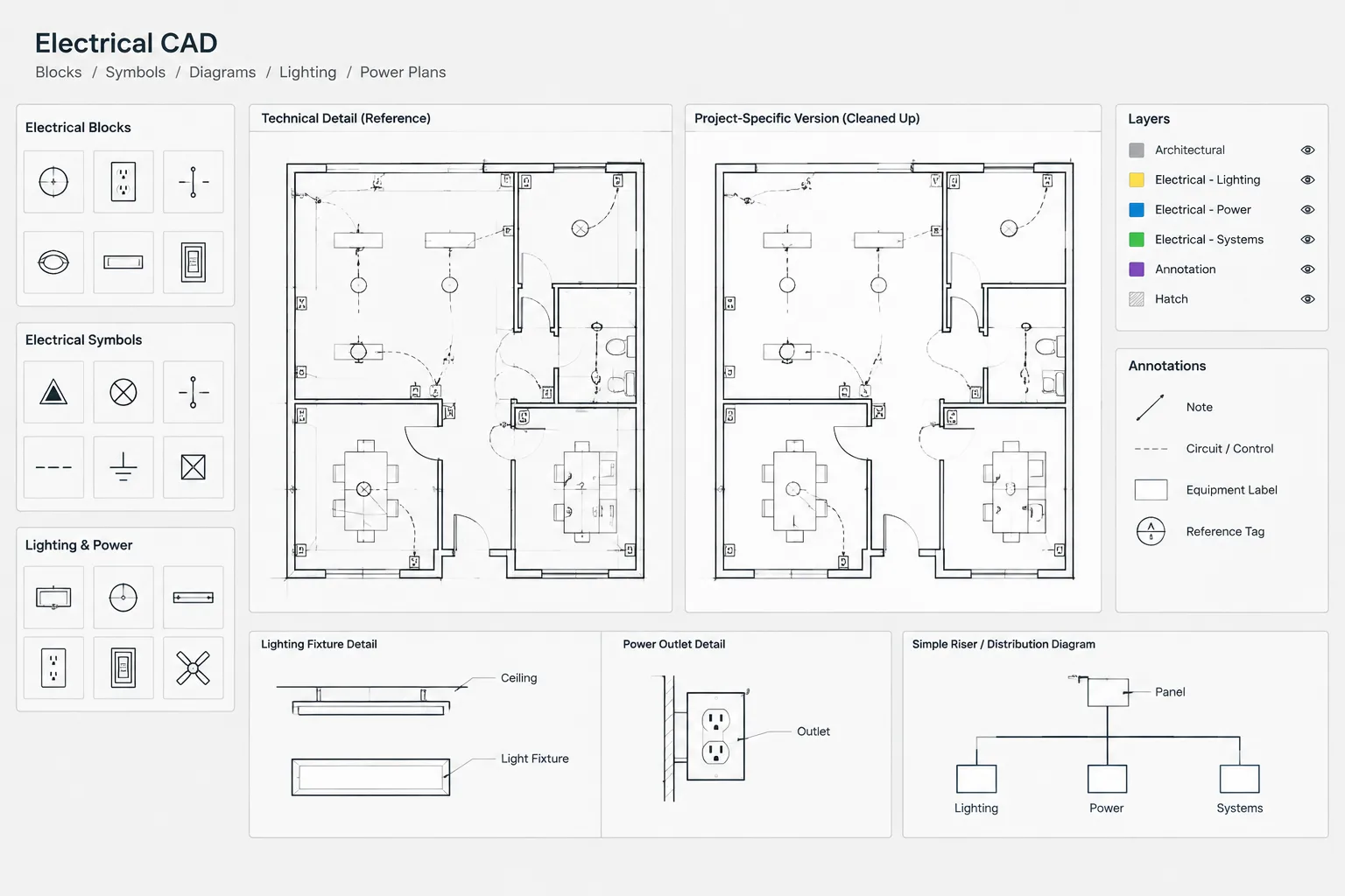
Reusing an electrical CAD detail is a documentation decision, not merely a copy-and-paste task. Even clean, professionally drawn source content may carry assumptions about equipment, interfaces, annotations, scale, or drawing conventions that do not apply to the current design.
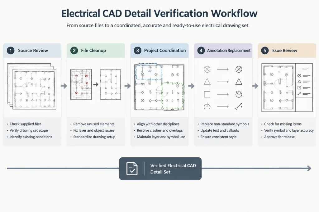
This verification workflow explains how to distinguish generic vs project-specific electrical details, retain useful drafting content, identify unresolved information, and establish a traceable review path before the adapted detail becomes part of an issued drawing set.
Generic electrical CAD details can save drafting time, but they should be treated as reference material rather than finished project documentation. A downloaded DWG may show a useful arrangement, symbol, mounting concept, or annotation structure while still containing assumptions that do not match the current project.
The safest workflow is not simply to insert a detail and edit the title. It is to identify what the detail is intended to communicate, separate reusable graphics from project-specific information, coordinate it with the rest of the drawing set, and record who must verify the remaining design decisions.
This guide presents a practical review process for CAD details used in electrical plans, diagrams, elevations, sections, and schedules. It focuses on drafting and documentation rather than field installation.
What Makes an Electrical CAD Detail Generic?
A generic detail illustrates a common condition without being fully coordinated for one particular building, system, product, or installation. It may show the relationship between components, a typical routing concept, an equipment arrangement, or a suggested method of annotation.
Generic content may include:
- Diagram symbols and connection lines
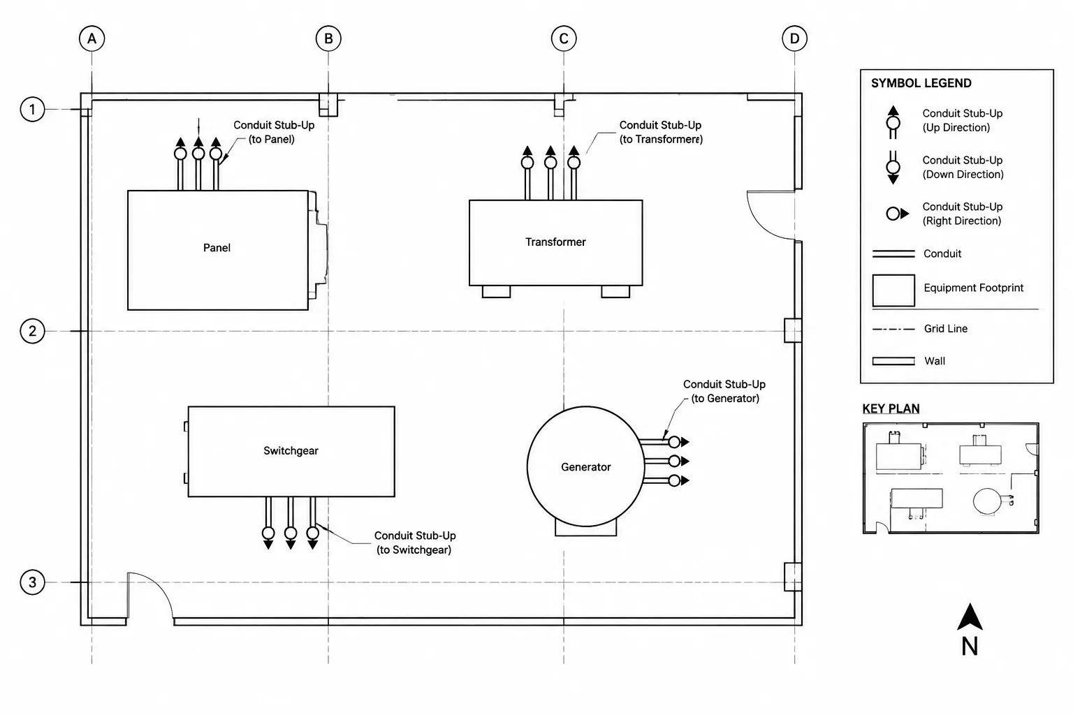
- Equipment outlines or simplified footprints
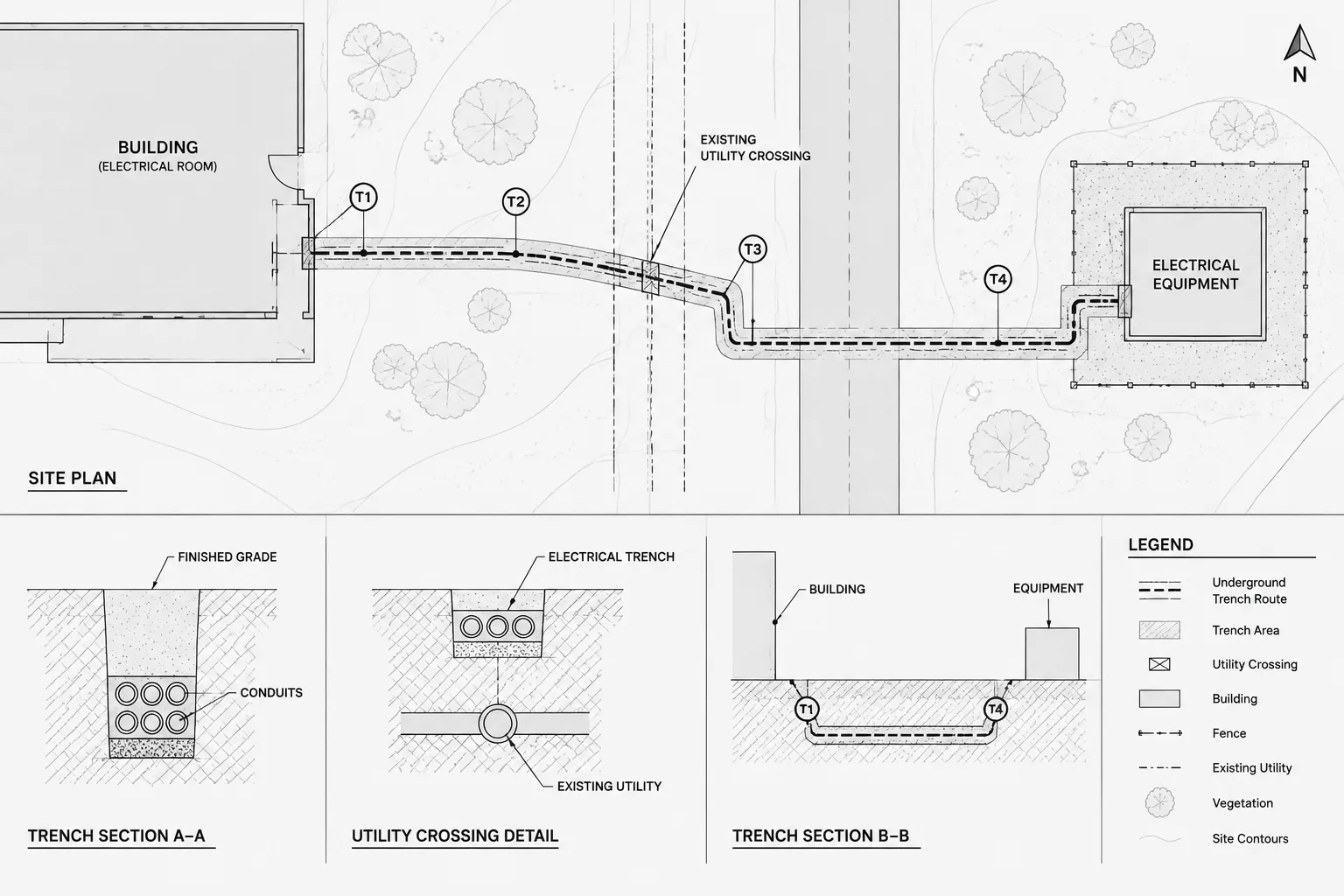
- Typical supports, sleeves, boxes, or raceway arrangements
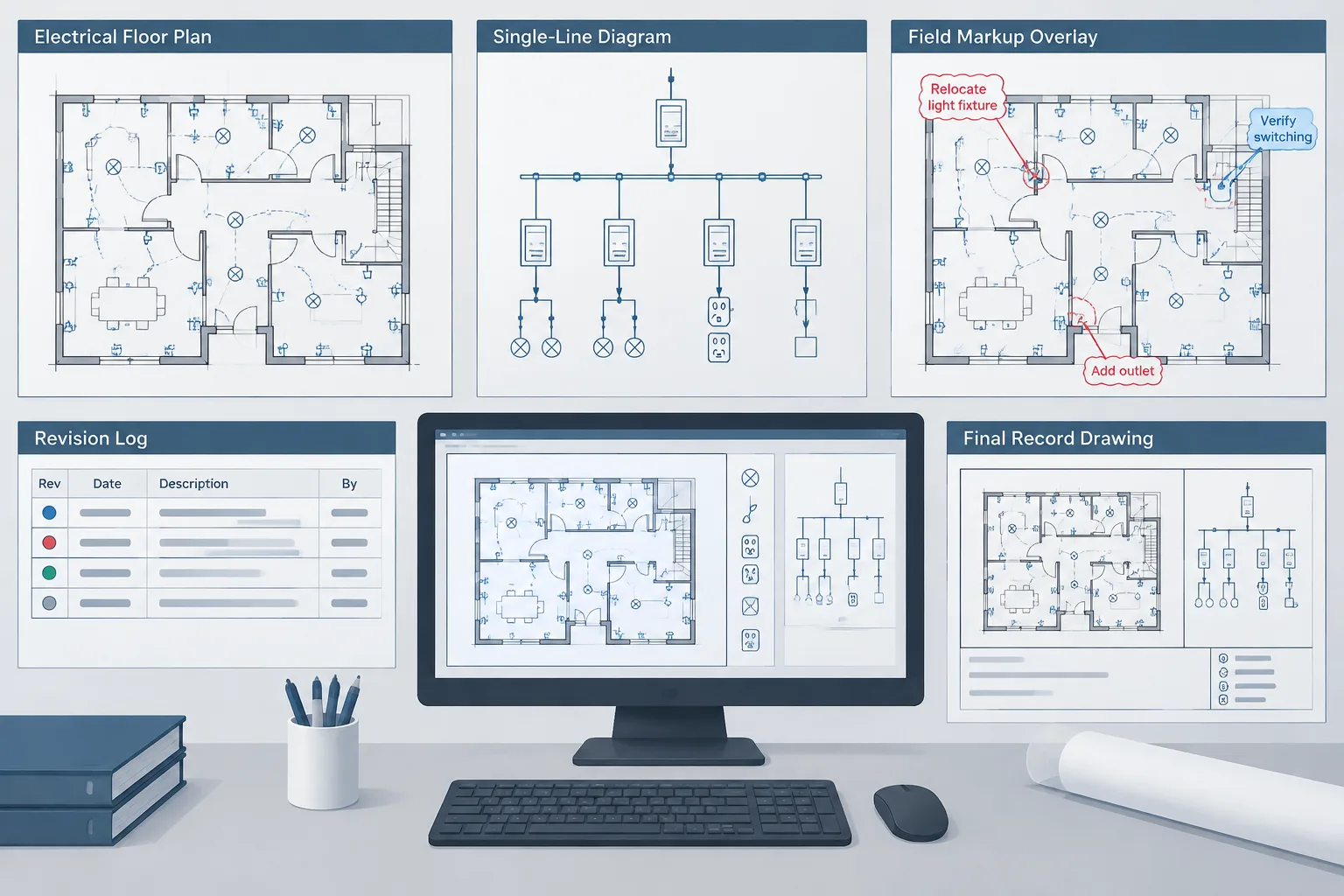
- Plan, elevation, section, or isometric views
- Placeholder tags and descriptive notes
- Sample leaders, dimensions, and detail titles
A project-specific detail, by contrast, has been checked against the actual design documents. Its equipment references, dimensions, interfaces, notes, and cross-references correspond to the project being issued.
A generic drawing can become part of a project detail, but insertion into the project file does not make it project-specific. Verification does.
Begin with the Detail’s Communication Purpose
Before editing geometry, write a short description of what the detail needs to explain. This prevents the drafting team from preserving irrelevant content merely because it came with the source file.

For example, the purpose might be to show:
- The relative location of an electrical box and an architectural surface
- The route of raceways through a coordinated opening
- The connection relationships between pieces of equipment
- The identification of conductors, terminals, or control points
- The interface between electrical work and another discipline
- The orientation and access side of floor-mounted equipment
If a line, note, or dimension does not support that purpose, determine whether it belongs in another detail or should be removed. A focused detail is easier to coordinate and less likely to communicate conflicting information.
Classify the Source Content Before Reusing It
Break the source detail into categories instead of reviewing it as one complete object. This makes hidden assumptions easier to find.
| Content category | Typical examples | Recommended review |
|---|---|---|
| Reusable graphics | Section markers, leaders, symbolic linework, simplified equipment shapes | Check scale, units, layers, lineweights, and clarity |
| Design information | Equipment relationships, circuit arrangement, raceway routing, connection logic | Verify against the project design and related calculations |
| Coordination information | Openings, supports, access areas, adjacent construction | Compare with architectural, structural, mechanical, and vendor documents |
| Product-dependent content | Terminal locations, enclosure configuration, mounting provisions | Confirm with current project submittals or manufacturer information |
| Project annotations | Tags, dimensions, notes, detail numbers, sheet references | Replace with controlled project data |
This classification also helps reviewers understand which portions are drafting conventions and which portions convey engineering intent.
Run a CAD File Health Check
Inspect external content before merging it into a production drawing. A visually simple detail can introduce layers, text styles, blocks, linetypes, or nested references that disrupt the project template.
Check units and scale behavior
Confirm the source drawing units and how the detail was intended to be displayed. Review annotation sizes, hatch scales, dimension styles, and block scaling. Do not rescale the entire detail until you understand whether the geometry is full size, diagrammatic, or deliberately not to scale.
Review layers and object properties
Map useful objects to approved project layers. Look for geometry with hard-coded colors, linetypes, or lineweights that will not respond correctly to the project plotting system. Remove empty or irrelevant source layers after the content has been transferred safely.
Inspect blocks and nested blocks
Check whether block names conflict with definitions already used in the project. Two blocks can have the same name but different graphics or attributes. Renaming, redefining, or rebuilding the source symbol may be safer than allowing an uncontrolled definition to overwrite project content.
Clean hidden and duplicate content
Look for coincident lines, stray objects, invisible attributes, distant geometry, unnecessary hatches, and clipped references. Keep a copy of the original source file so cleanup does not destroy the only record of what was received.
Replace Assumptions with Project References
Generic notes often contain implied decisions. Phrases such as “typical,” “as required,” or “coordinate in field” can be appropriate in limited contexts, but they should not be used to conceal information that the drawing set is expected to define.
Review every note and ask:
- Does it identify a project responsibility clearly?
- Does it agree with the specifications and schedules?
- Does it reference equipment or materials that actually appear in the project?
- Does another drawing already define this condition differently?
- Could a reader mistake an illustrative component for a required component?
- Is the note still necessary after the detail is coordinated?
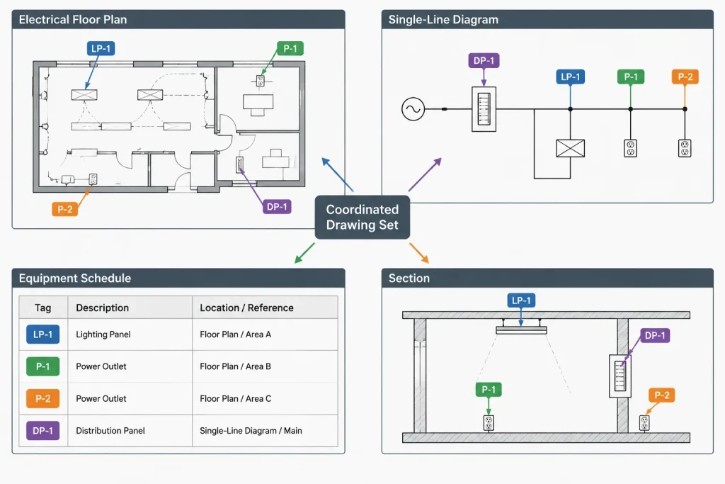
Replace placeholder equipment tags with project identifiers. Connect detail references to the appropriate plans, one-lines, risers, schedules, or enlarged views. If final information is unavailable, use an established project placeholder convention and track it for resolution rather than inventing data.
Decide What Should Be Drawn to Scale
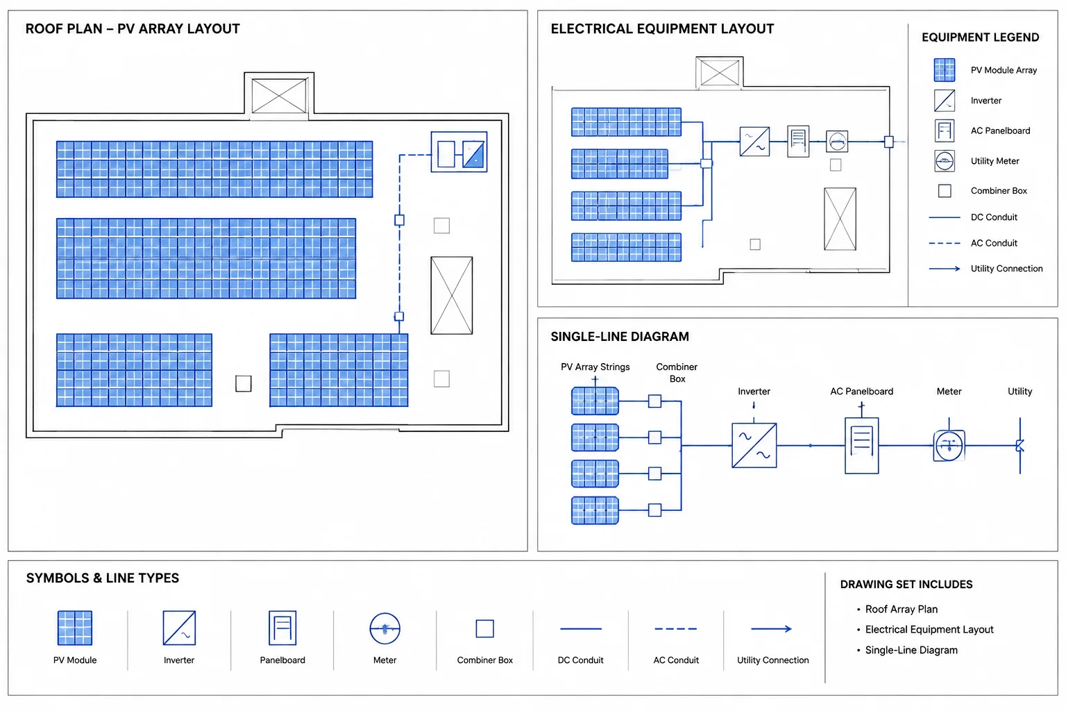
Not every electrical detail is intended to be measured. Equipment layouts, wall elevations, and coordinated sections may need scaled geometry so they align with architectural conditions. Single-line diagrams and wiring concepts are commonly diagrammatic because their purpose is to communicate relationships rather than physical distance.
Make the distinction visible. A diagrammatic detail should not include misleading dimensions or realistic spacing that appears authoritative. A scaled detail should use verified project geometry and should identify the view, orientation, and references needed to understand its location.
Avoid combining a scaled background with symbolic components in a way that suggests false precision. If symbols are enlarged for readability, the graphic convention should remain clear.
Coordinate the Detail Across the Drawing Set
A correct standalone detail can still create a documentation conflict. Compare it with every drawing that describes the same equipment or interface.
- Plans: Confirm location, orientation, tag, circuit reference, and nearby conditions.
- Single-line diagrams: Confirm source-to-load relationships and equipment identification.
- Schedules: Confirm that names and type designations use the same terminology.
- Elevations and sections: Confirm access side, mounting relationship, and interfaces with construction.
- Other disciplines: Confirm openings, supports, equipment zones, and shared spaces.
- Specifications and submittals: Confirm that product-dependent graphics do not contradict written or supplier information.
Use one controlled identifier for each item wherever possible. If a plan calls an enclosure by one tag and the detail uses another, readers may assume they are different components.
Use a Detail Applicability Record
For larger projects or shared detail libraries, maintain a simple record showing why a detail is included and what has been checked. This can be a spreadsheet, drawing register, or controlled database.
| Record field | Purpose |
|---|---|
| Detail title and identifier | Connects the record to the drawing set |
| Source | Identifies whether content came from an office library, consultant, vendor, or previous project |
| Intended use | Explains the condition the detail documents |
| Project locations | Lists where the condition occurs |
| Items requiring verification | Tracks unresolved dimensions, interfaces, products, or responsibilities |
| Related documents | Points reviewers to plans, schedules, diagrams, or other disciplines |
| Review status | Shows whether the detail is proposed, coordinated, approved for issue, revised, or retired |
This record is especially valuable when several similar details exist. It helps prevent an outdated library detail from returning to the set after a project-specific version has already been developed.
Preserve Source Traceability Without Cluttering the Sheet
The final drawing does not need to display internal library history, but the project team should be able to trace where content originated. Keep the untouched source in a controlled reference location, and document significant changes through the project revision workflow.
Avoid placing dates, initials, or revision comments inside reusable block geometry unless that information is intended to appear on every plotted instance. Administrative data is usually better managed through file properties, registers, issue records, or controlled attributes.
Final Review Checklist
Before issuing a detail adapted from generic CAD content, confirm that:
- The purpose of the detail is clear.
- Source units, layers, blocks, and annotation have been checked.
- Placeholder tags and references have been replaced or formally tracked.
- Product-dependent geometry has been verified or shown generically.
- Scaled and diagrammatic information are not visually confused.
- Notes agree with the project documents and do not hide unresolved design decisions.
- Equipment identifiers match plans, schedules, and diagrams.
- Interfaces with other disciplines have been reviewed.
- Unused source content and hidden objects have been removed.
- The detail has an identifiable review and revision status.
Generic Details Are Starting Points, Not Conclusions
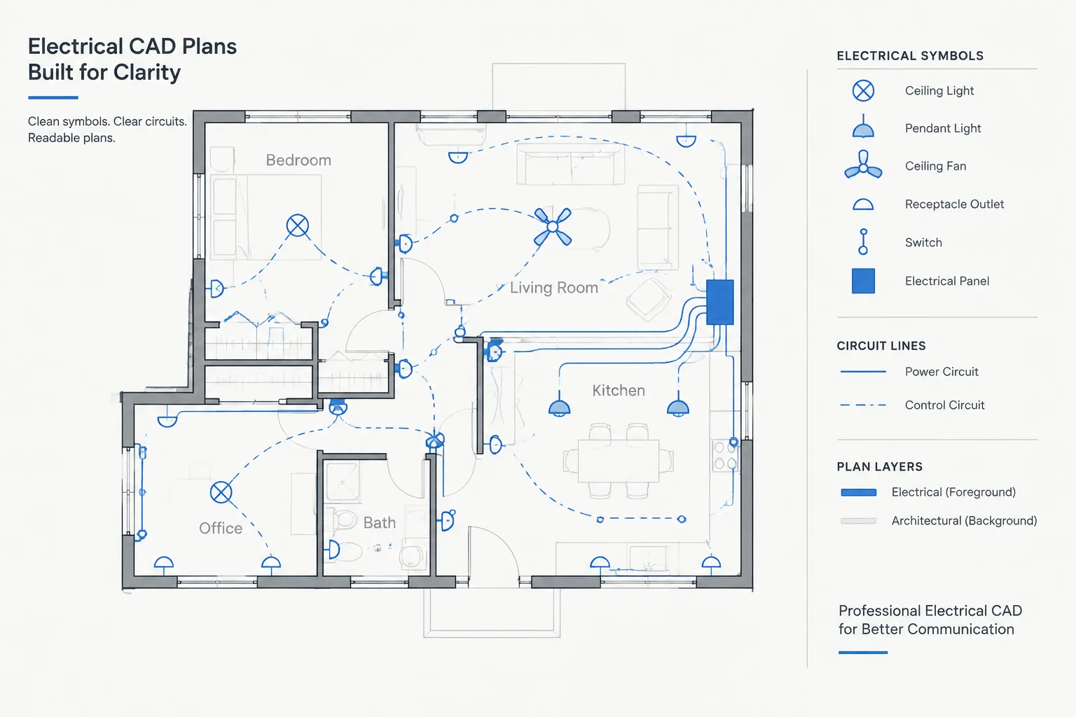
A well-maintained CAD library improves consistency and reduces repetitive drafting, but its value depends on disciplined use. The best workflow preserves reusable graphic content while challenging every project assumption carried with it.
By separating drafting conventions from design information, coordinating the detail across the drawing set, and recording unresolved items, teams can turn generic electrical CAD details into clear project documentation without implying that unverified content is ready for construction.
A Practical Status Model for Reused Details
Clear status language helps prevent an imported detail from appearing more complete than it is. A useful internal workflow can distinguish among source content, adapted content, and verified project content.
- Source content: The untouched file or library item received from its original location.
- Adapted content: Geometry and annotations transferred into the project environment but still undergoing coordination.
- Verified project content: A detail reviewed against the applicable plans, schedules, diagrams, product information, and discipline interfaces.
These descriptions do not replace the project team’s formal review terminology. Their purpose is to make the transition from reference material to controlled documentation visible during drafting.
Separate Graphic Completion from Technical Verification
A detail can look finished while still containing unresolved design information. Plot quality, aligned leaders, consistent text, and clean linework indicate graphic completion, but they do not confirm that equipment relationships, mounting conditions, tags, or cross-references are correct.
Review comments should therefore identify the kind of action required. Drafting corrections can address layer mapping, symbol clarity, annotation placement, and block behavior. Technical or coordination questions should be assigned to the appropriate project reviewer rather than silently resolved through graphic editing.
Use Exceptions to Drive the Review
Instead of asking only whether a typical detail appears acceptable, compare its assumptions with the actual project condition. Record each mismatch as an exception, identify the controlling project reference, and note who is responsible for resolving it.
This exception-based approach is especially useful when one generic detail is proposed for several locations. If the locations have different equipment, construction interfaces, orientations, or access conditions, the team can decide whether controlled variations are needed rather than forcing every condition into one misleading typical detail.
Frequently Asked Questions
When does a generic CAD detail become project-specific?
It becomes project-specific after its relevant geometry, identifiers, notes, interfaces, and references have been checked against the current project documents. Moving the detail into a project file or changing its title does not complete that verification.
Should the original downloaded or library file be edited directly?
Keep an untouched source copy in a controlled location. Perform cleanup and project adaptation in a separate working file or controlled project environment so the team can compare changes and trace the content’s origin.
How should unresolved information appear during drafting?
Use the project’s established placeholder and issue-tracking conventions. The unresolved item should be visible to reviewers, assigned for verification, and prevented from being mistaken for approved project information.
Can one typical detail represent several project locations?
Yes, when the documented condition and relevant interfaces are genuinely consistent. If equipment, orientation, adjacent construction, access relationships, or responsibilities vary, separate details or clearly controlled variations may communicate the design more accurately.
Who should verify product-dependent geometry?
The project team should route it to the party responsible for confirming the applicable design and product information. A drafter can identify conflicts and manage the drawing content, but should not invent terminal locations, mounting provisions, or enclosure arrangements that have not been verified.
Leave a Reply
You must be logged in to post a comment.