
Electrical feeder routing plans in CAD translate distribution relationships into coordinated plan graphics. They show how major electrical pathways relate to equipment locations, building backgrounds, level changes, and drawing boundaries while leaving verified electrical data under the control of diagrams, schedules, and project documentation.
This reference explains how to organize route linework, feeder tags, continuation markers, vertical transitions, layers, and quality-control reviews. The goal is not to prescribe an installation path, but to help drafting teams produce plans that remain readable and traceable throughout design coordination and revision.
An electrical feeder routing plan connects two kinds of project information: the electrical distribution relationships shown on a single-line diagram and the physical pathways coordinated through the building or site. It helps the drawing team communicate where major feeders are intended to travel without turning the floor plan into a wiring diagram.
The plan may show feeders serving panelboards, transformers, switchboards, motor control equipment, distribution equipment, or other significant loads. Its exact scope varies by project. Some drawing sets show only primary distribution routes, while others include a broader group of feeders and raceway systems. In either case, the drafting objective is the same: create traceable route graphics that agree with the rest of the electrical documents.
A feeder routing plan is documentation, not a substitute for engineering decisions or field verification. Conductor information, raceway requirements, equipment connections, routing constraints, and installation details must come from verified project sources.
What a Feeder Routing Plan Should Communicate
A useful routing plan answers several practical questions:
- Where does the feeder begin and end?
- What tag connects the route to the single-line diagram or feeder schedule?
- Does the pathway run overhead, below grade, below a floor, or within a designated shaft?
- Where does the route change level or continue onto another drawing?
- Which portions are diagrammatic, concealed, existing, future, or by others?
- Where is additional information provided in a section, detail, profile, or enlarged plan?
The plan does not need to show every physical bend. In many construction drawing sets, feeder paths represent routing intent rather than an exact installation geometry. The notes, legend, and linework should make that distinction clear.
Start with Verified Source Information
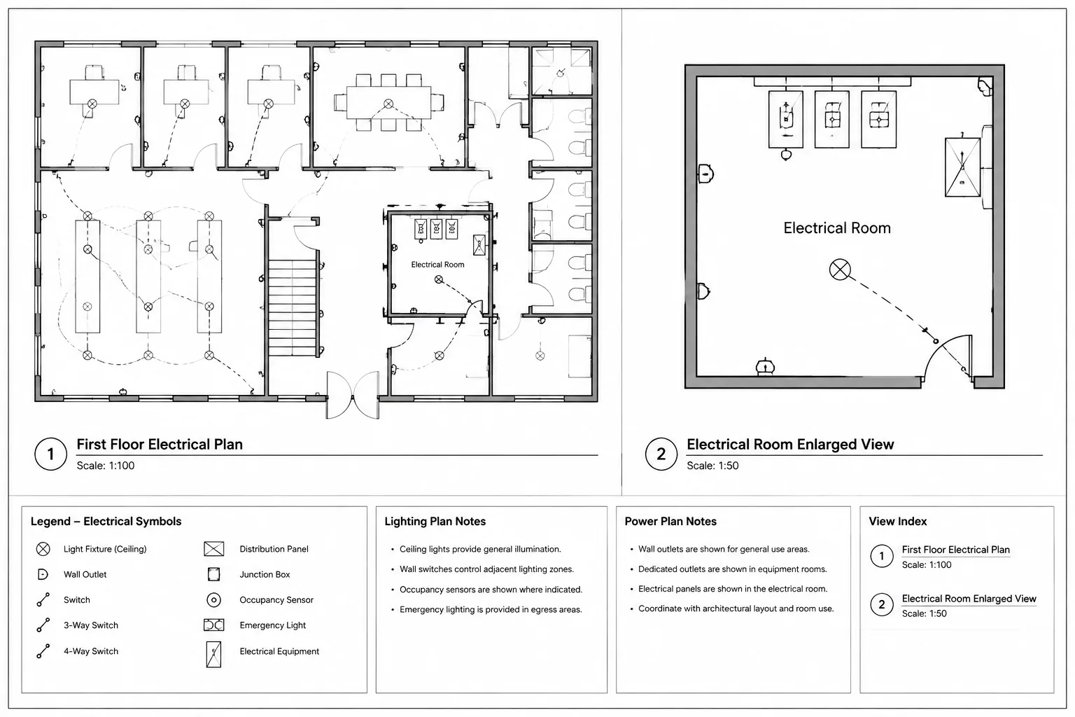
Before drawing paths, assemble the current coordination sources. These commonly include the single-line diagram, feeder schedule, panel or equipment schedules, electrical room plans, architectural backgrounds, structural information, and pathway coordination drawings.
Create a working list of feeder relationships. For each route, identify the source equipment, destination equipment, feeder designation, pathway description if provided, and any drawing references. Do not infer missing electrical data from the apparent size or location of a CAD block. A generic equipment footprint does not establish a connection method or feeder requirement.

Resolve Equipment Identities First
Route linework becomes unreliable when equipment tags differ between plans and diagrams. Confirm that source and destination identifiers match the project naming convention before connecting them. Similar names, temporary tags, and duplicated identifiers are common coordination problems, especially when backgrounds or vendor drawings have changed.
If an equipment designation is unresolved, flag it for review rather than silently creating a new identifier. A clearly marked coordination item is safer than a polished route attached to the wrong equipment.
Choose a Consistent Route Graphic
Feeder routes should be visually distinct from architectural walls, branch-circuit arcs, control wiring, and underground utilities. The graphic system may use a dedicated linetype, lineweight, color, layer, or combination of these properties. The plotted result matters more than the screen color.
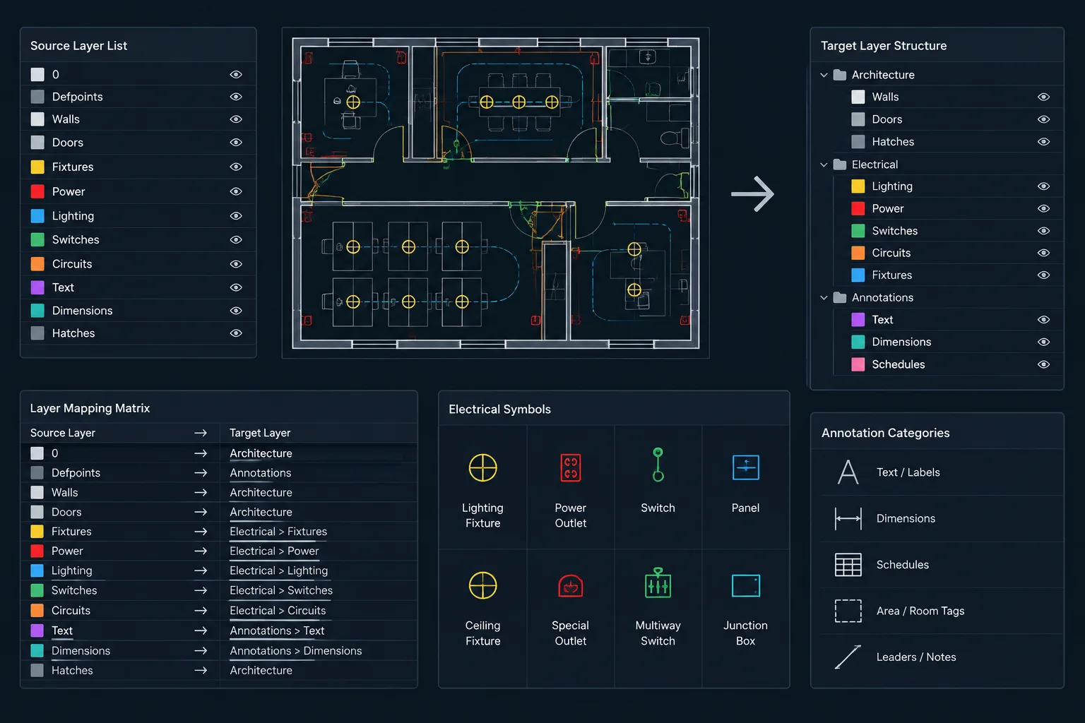
A practical layer structure can separate route categories that require independent display control. Possible categories include:
- Normal-power feeder routes
- Backup or alternate-source feeder routes
- Underground or below-slab routes
- Existing feeder routes
- Future or spare pathways
- Route tags and annotations
- Vertical transition symbols
Do not create more categories than the drawing can explain. If two route types look different, the legend should state what the difference means.
Use Polylines Deliberately
Continuous polylines are generally easier to select, revise, measure, and audit than collections of disconnected line segments. Keep vertices purposeful and avoid tracing every minor architectural offset unless it affects coordination.
Route geometry should be clean enough to reveal accidental gaps, duplicate segments, and ambiguous intersections. Where several feeders share a conceptual pathway, the drawing team may use parallel lines, a grouped route, or a pathway identifier linked to a schedule. The selected approach should remain readable at the final plot scale.
Feeder Tags and Route Identification
A feeder tag provides the link between plan geometry and electrical data recorded elsewhere. It may contain a feeder identifier, a source-to-destination reference, a pathway tag, or another project-defined code. Avoid placing a long string of conductor and raceway data repeatedly along a route if the same information is controlled in a verified schedule.

Place tags where readers can find them without following a long line across the entire sheet. Useful locations include near the source, near the destination, after a major transition, and on each sheet where the route continues. Repeated tags must remain identical.
| Plan element | Primary purpose | Coordination source |
|---|---|---|
| Route line | Shows intended physical pathway | Plans, backgrounds, and coordination information |
| Feeder tag | Identifies the documented feeder | Single-line diagram or feeder schedule |
| Equipment tag | Identifies source or destination | Plans, schedules, and equipment lists |
| Transition symbol | Shows a change in level or drawing view | Risers, sections, shafts, and floor plans |
| Detail reference | Directs the reader to added routing information | Sections, profiles, or enlarged plans |
| Status graphic | Distinguishes existing, new, future, or removed work | Project scope and phasing documents |
Document Vertical Transitions Clearly
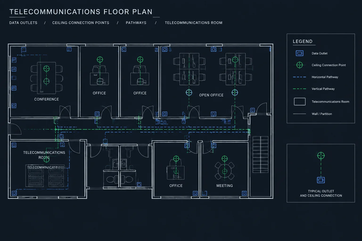
A route that disappears at a wall, shaft, or equipment room boundary can be difficult to interpret. Use a consistent transition symbol to show when a feeder rises, drops, enters a shaft, or continues between levels. Pair the symbol with a destination reference, level name, or drawing reference when needed.
For multi-story projects, compare each transition across adjacent floor plans. A route entering a shaft on one level should have a corresponding continuation on the next applicable level or a clear explanation of where it goes. Riser diagrams can describe the electrical relationship, but they do not automatically confirm that the floor-plan pathway is coordinated.
Show Route Continuations Across Sheets
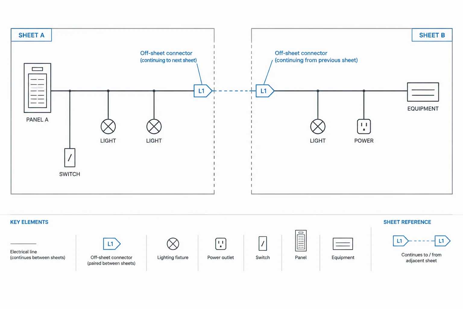
Large plans often divide one route among several sheets. Do not allow feeder linework to stop at a match line without identification. Add a continuation reference that points to the correct sheet, area, or view. Repeat the feeder tag on both sides of the transition.
The same principle applies when a feeder moves from a building plan to a site plan, underground profile, roof plan, or enlarged electrical room plan. The reader should not have to guess which line continues the route.
Coordinate Shared Pathways Without Overcrowding
Multiple feeders may pass through the same corridor, shaft, trench, or electrical room. Drawing every route directly on top of another can hide information. Spreading them too far apart can falsely suggest separate pathways.
Choose a representation based on the purpose of the sheet:
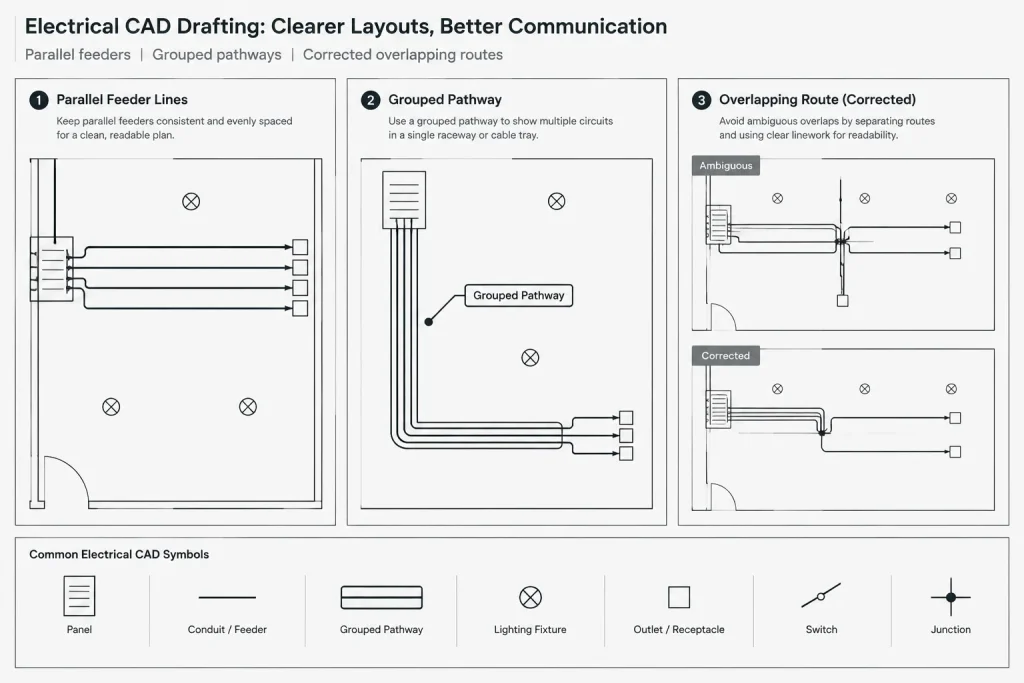
- Parallel route lines: Useful when individual feeder continuity must remain visible.
- Grouped pathway line: Useful when several feeders share a documented pathway and are identified in a route or conduit schedule.
- Keyed callout: Useful in congested areas where a detail or enlarged plan provides the full breakdown.
- Diagrammatic offset: Useful when lines must be separated for readability, provided the drawing explains that the offset is graphic rather than physical.
Avoid using a single unlabeled line for several feeders unless another drawing or schedule clearly defines what the line represents.
Separate Routing Intent from Installation Detail
Feeder routing plans should communicate the required level of coordination without implying unsupported precision. A route line centered in a corridor may indicate a general pathway rather than an exact raceway position. Conversely, a coordinated equipment room or trench drawing may require more precise alignment with openings, sleeves, pads, or pathway zones.
Use notes and references to establish the drawing’s level of intent. Do not add unverified bend geometry, raceway quantities, conductor data, elevations, or penetration locations simply to make the plan appear complete.
CAD Quality-Control Workflow
Review the routing plan both visually and by feeder identity. A productive check can follow these steps:
- Highlight one feeder at a time from source to destination.
- Confirm that its tag matches the single-line diagram and applicable schedule.
- Verify that source and destination equipment appear on the correct plans.
- Check every sheet boundary, level change, and view transition.
- Review route intersections for false connections or ambiguous overlaps.
- Confirm that status graphics match project scope and phasing.
- Plot the sheet and verify that routes remain distinguishable from backgrounds and branch circuiting.
- Search for orphaned tags, routes without tags, and duplicated route geometry.
Automated selection, layer isolation, and object-property review can help, but they do not replace a source-to-destination check. A geometrically continuous line can still carry the wrong feeder designation.
Common Drafting Problems
- Routes disagree with the single-line diagram: The physical plan and distribution relationship were revised independently.
- Tags appear only once: Readers cannot identify the route after it crosses a sheet or floor boundary.
- Lines end without explanation: A missing transition or continuation reference makes the route look incomplete.
- Branch circuits and feeders look alike: The graphic hierarchy does not distinguish distribution pathways from local circuiting.
- Routes are drawn over equipment: Connection intent is obscured by blocks, hatches, or masking.
- Too much data is repeated: Long route notes become difficult to maintain when schedules change.
- Existing and new work are mixed: The drawing does not communicate scope status consistently.
A Coordinated Plan Is More Than a Route Line
A successful electrical feeder routing plan creates a reliable chain between equipment locations, distribution diagrams, schedules, and physical pathway references. Clean linework is important, but identity and continuity are more important. Every major route should be traceable, every transition should be understandable, and every tag should point back to verified project information.
When the CAD workflow treats routes as coordinated documentation rather than decorative lines, feeder plans become easier to review, revise, plot, and use alongside the rest of the electrical drawing set.
Using the Routing Plan During Drawing Review
A feeder routing plan is most useful when reviewers can follow each documented path without relying on screen color, memory, or assumptions about the building layout. Review the plotted sheet alongside the current single-line diagram, schedules, equipment plans, and relevant pathway views.
Check Identity Before Geometry
A visually convincing route can still be incorrect if its source, destination, or feeder tag does not agree with the controlled project information. Confirm equipment identities and route references before refining offsets, line spacing, or annotation placement.
Review the Plan as Part of a Drawing Set
Do not evaluate a routing sheet in isolation. Confirm that feeder identities remain consistent wherever they appear, including electrical room plans, site plans, riser diagrams, schedules, enlarged views, and continuation sheets. A route should retain the same documented meaning when it passes between these views.
Preserve Revision Traceability
When equipment locations or distribution relationships change, update route geometry and associated references together. Layer isolation, property filters, and tag searches can help locate affected objects, but the final review should still trace the complete relationship from source to destination.
Keep Graphic Conventions Maintainable
Use a limited set of route styles that can be explained by the legend and reproduced consistently by the project team. If a route appearance has no defined meaning, it can create uncertainty during plotting, coordination, and later revisions.
- Use verified identifiers: Keep feeder and equipment tags aligned with controlled project sources.
- Make transitions visible: Identify changes between sheets, levels, and drawing types.
- Check plotted clarity: Confirm that routes remain distinct from backgrounds and other electrical linework.
- Flag unresolved information: Record coordination questions instead of filling gaps with assumptions.
- Avoid unsupported precision: Show routing intent at the level established by the project documents.
Frequently Asked Questions
What is the difference between a feeder routing plan and a single-line diagram?
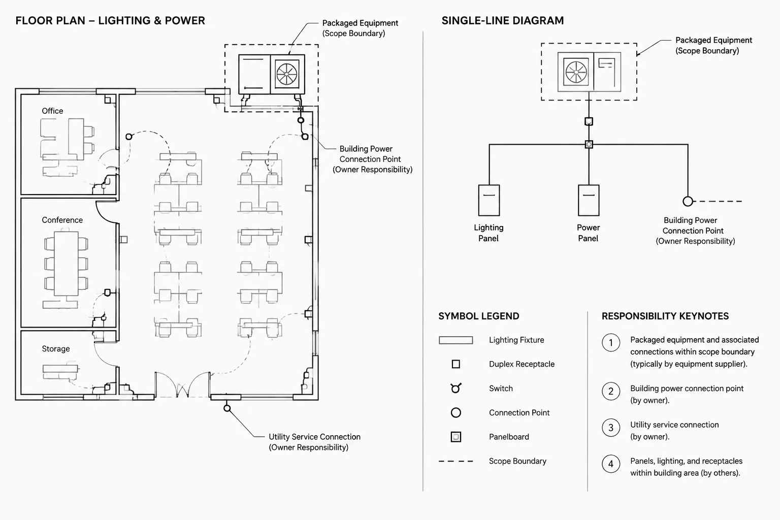
A single-line diagram communicates electrical distribution relationships in diagrammatic form. A feeder routing plan places the associated pathways in a physical plan context so readers can understand intended travel, equipment locations, transitions, and drawing continuations.
Should a feeder route show every bend?
Not necessarily. The required detail depends on the purpose of the drawing and the available coordination information. General plans often communicate routing intent, while coordinated rooms, trenches, shafts, or enlarged views may show more precise pathway relationships. The graphics and notes should make the intended level of accuracy clear.
Where should feeder information be stored?
Route tags should connect plan geometry to the verified diagram, schedule, or other controlled source. Repeating extensive electrical data along every route can make revisions difficult and create conflicts when documents change.
How should feeders continuing onto another sheet be shown?
Use a clear continuation reference and repeat the feeder identity where the route leaves and enters the applicable views. The line should not stop at a match line or view boundary without explaining where it continues.
Can several feeders share one route graphic?
They can be represented by a grouped pathway when the drawing set clearly identifies what the group contains. If individual continuity is important, separate route lines or a keyed detail may be more readable. An unlabeled shared line should be avoided.
Why must feeder plans be checked in plotted form?
Screen colors and layer settings may not reflect the final drawing hierarchy. Plot review reveals whether route lines, tags, transitions, backgrounds, and status graphics remain distinguishable at the intended sheet presentation.
Leave a Reply
You must be logged in to post a comment.