
Electrical equipment schedules in CAD help organize the identifiers and references that connect equipment across a drawing set. Their usefulness depends less on the number of columns than on whether each entry agrees with the plans, diagrams, details, specifications, and other controlled project documents.
This guide explains how to define schedule scope, select meaningful fields, maintain stable equipment tags, choose an appropriate CAD table method, and review the finished schedule for coordination conflicts. It is intended as a drafting and documentation reference; project requirements and technical characteristics must still be verified by the responsible design team.
An electrical equipment schedule is more than a list of products. It is a drawing-based coordination tool that connects equipment identifiers with plan locations, diagram relationships, installation details, and project requirements. When the schedule is organized well, reviewers can trace an item from its symbol on a floor plan to its electrical source and supporting documentation without guessing.
Schedules can also become a source of conflict. A tag may appear on the plan but not in the table, a description may disagree with the single-line diagram, or copied rows may retain information from an earlier design. A reliable CAD workflow treats the schedule as controlled project data rather than decorative table content.
What an Electrical Equipment Schedule Does
The schedule provides a structured index of selected electrical equipment shown in the drawing set. Depending on project scope, it may cover distribution equipment, transformers, disconnects, control panels, packaged electrical assemblies, specialty devices, or equipment furnished under another discipline but requiring electrical coordination.
It does not need to repeat every note, rating, dimension, or requirement found elsewhere. Its primary value is to identify equipment consistently and direct the reader toward the drawings and documents that contain the complete information.
An effective schedule helps answer several practical questions:
- What is the equipment called on the drawings?
- Where is it shown?
- What source or upstream equipment serves it?
- Which plan, diagram, elevation, or detail provides additional information?
- Which characteristics must be coordinated with specifications or vendor information?
- Is the item new, existing, relocated, future, or otherwise subject to a project-specific status?
Define the Schedule Scope Before Building the Table
Before drawing rows and columns, decide what belongs in the schedule. A common drafting mistake is to combine unrelated information merely because it can fit in one table. A distribution equipment schedule, mechanical equipment connection schedule, and specialty system equipment list may require different fields and different ownership.
Start by identifying the schedule’s purpose and audience. A schedule intended to coordinate electrical distribution equipment may emphasize equipment tags, sources, locations, and diagram references. A connection schedule supporting mechanical coordination may emphasize the equipment identifier supplied by the mechanical drawings, the electrical connection designation, source reference, and responsibility notes.
Keep the title specific. A table labeled simply “Equipment Schedule” can be ambiguous when a drawing set contains equipment from several disciplines. Clear naming also helps when schedule references appear in notes or callouts.
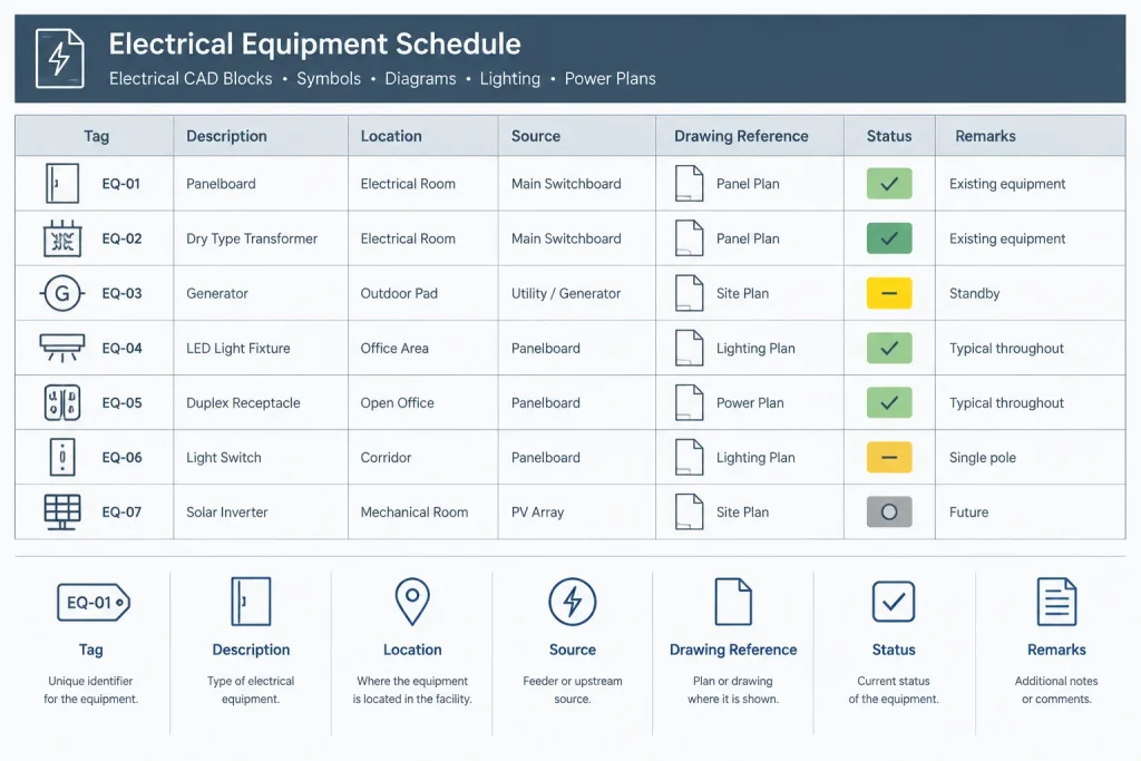
Useful Schedule Fields
The appropriate columns depend on the project, but each field should have a defined purpose. Avoid filling the table with information that cannot be maintained reliably throughout design and issue cycles.
| Field | Coordination purpose | Drafting caution |
|---|---|---|
| Equipment tag | Provides the primary identifier used across drawings. | Match capitalization, punctuation, and prefixes everywhere. |
| Description | States the equipment’s functional identity in plain language. | Do not use the description as a substitute for specifications. |
| Location | Helps readers find the item by room, area, level, or site zone. | Coordinate with current architectural room names and numbers. |
| Source | Identifies the upstream panel, switchboard, transformer, or other documented source. | Confirm that the same relationship appears on diagrams and schedules. |
| Plan reference | Directs readers to the plan view containing the equipment. | Update the reference when views move between sheets. |
| Diagram or detail reference | Connects the row to one-lines, risers, elevations, or installation details. | Avoid references that lead only to another unresolved reference. |
| Status | Distinguishes new, existing, relocated, future, or project-defined conditions. | Use the same status terminology and graphics throughout the set. |
| Remarks | Records a concise exception or coordination instruction. | Move lengthy requirements into keyed notes or specifications. |
Technical characteristics may also appear when they are part of the project documentation strategy. Any rating, configuration, enclosure designation, connection requirement, or other technical value must come from verified design information. Do not populate missing cells by assumption or by copying a superficially similar item.
Create a Stable Equipment Identification System
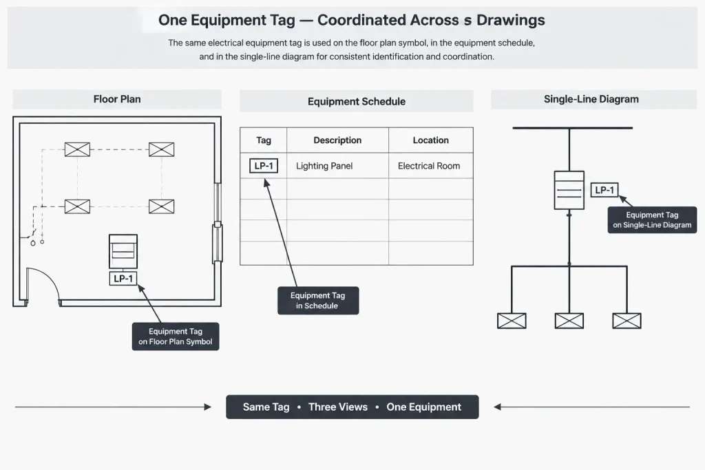
The equipment tag is the link between the schedule and the rest of the drawing set. It should be unique within the project’s agreed naming system and remain stable unless there is a deliberate reason to change it.
A tag may contain a functional prefix, an area designation, a sequence, or another project-defined element. The exact structure is less important than consistent use. Avoid allowing separate contributors to develop competing names for the same equipment. For example, the floor plan, single-line diagram, equipment elevation, and schedule should not use different abbreviations for one item.
Equipment tags should remain identifiers rather than compressed specifications. Packing too much technical meaning into a tag makes future revisions difficult and increases the chance that the tag becomes inaccurate while still appearing authoritative.
Coordinate the Schedule with Other Drawings
Floor and Site Plans
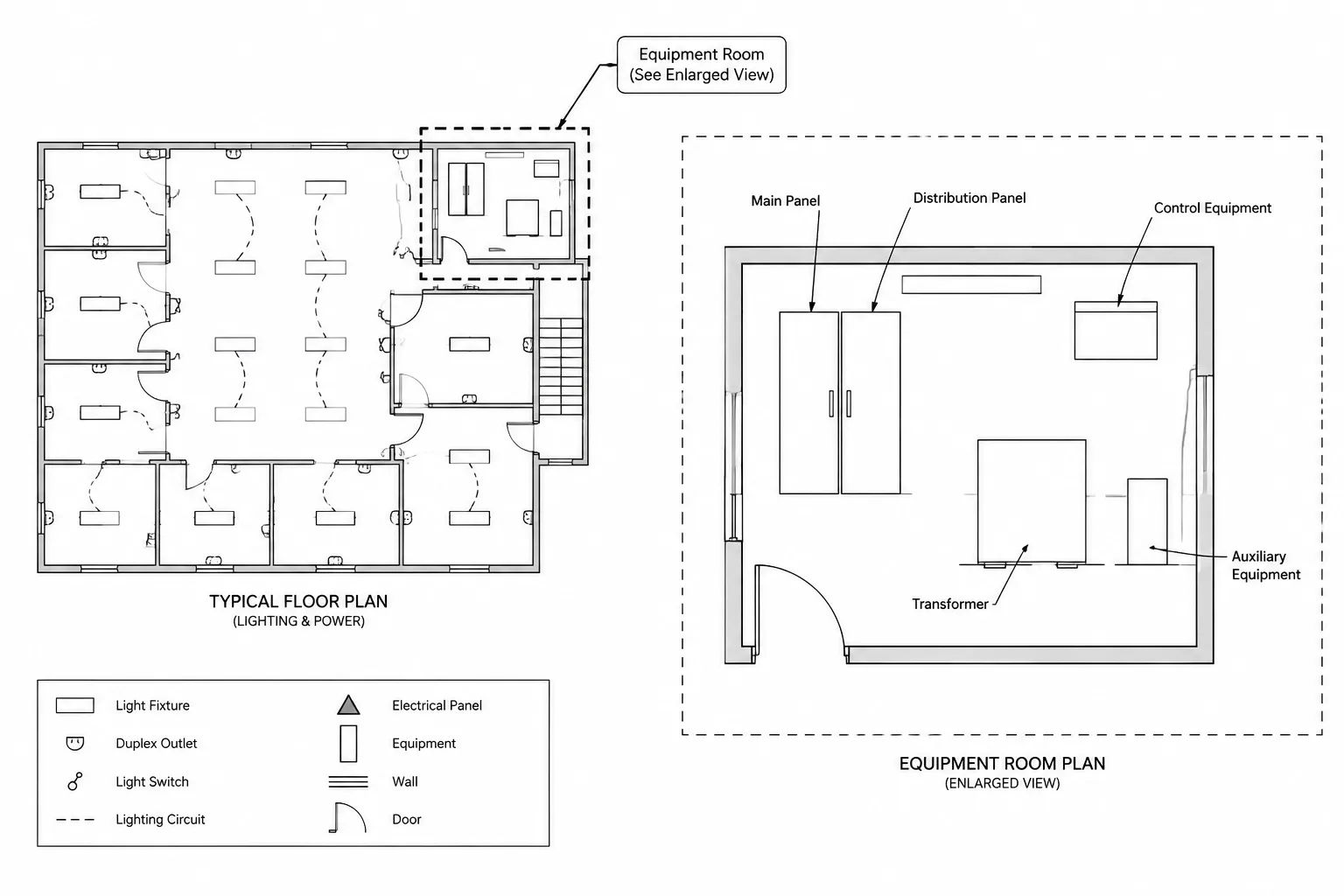
Verify that every scheduled item expected to have a physical location appears on the appropriate plan. Check the tag, orientation, room or area, and nearby access information. If a symbol is offset for readability, use a clear leader or another established graphic method so that its intended location is not mistaken.
Single-Line and Riser Diagrams
Compare equipment names and source relationships. If the schedule identifies an upstream source, the diagram should support that relationship. Equipment appearing only on a diagram may still require a schedule row if the schedule is intended to index the complete distribution system.
Panel and Feeder Schedules
Cross-check source names, load identifiers, feeder references, and destination tags. The equipment schedule should not become an independent version of information already controlled by another schedule. Where practical, use references rather than duplicating fields that are likely to change.
Elevations, Sections, and Details
Equipment dimensions, mounting arrangements, access zones, and interface points may be clearer in an elevation or detail than in the main schedule. Reference those views instead of overloading schedule remarks. Any generic detail must be checked against the actual equipment and project conditions before use.
Specifications and Vendor Information
Drawings and specifications should complement one another. The schedule may identify an item and summarize selected coordination data, while the specification carries broader performance, submittal, execution, and quality requirements. Vendor documents can inform the design, but unverified vendor values should not be presented as final project requirements.
Choose a CAD Table Method
Electrical equipment schedules may be created as native CAD tables, attributed block assemblies, linked data, or carefully structured text and linework. Each method has different editing and exchange implications.
- Native tables: Useful for consistent cells, alignment, and row management when supported by the project workflow.
- Attributed blocks: Helpful when repeated row structures need controlled fields, but attribute extraction and editing procedures must be understood by the team.
- Linked data: Can reduce repeated entry when a trusted external source controls the information, but broken links and unexpected formatting changes require review.
- Text and linework: Portable and visually predictable, although manual editing can increase the risk of misaligned or outdated entries.
Whichever method is selected, prioritize dependable plotting and straightforward revision. Do not rely on a data connection or custom object unless the recipients can open, review, and maintain it as required by the deliverable workflow.
Draft for Readability
Keep column headings brief but unambiguous. Align similar data consistently, provide enough visual separation between rows, and use wrapping deliberately. Excessively wide schedules can force text to become too small or make the sheet difficult to navigate.
If the table becomes crowded, reconsider its structure before reducing readability. Separate schedules by equipment class, move extended notes elsewhere, or place the schedule on a dedicated sheet. Repeated header rows can help when a schedule is split, but each segment should make its continuation and scope clear.
Apply a restrained graphic hierarchy. Titles, headings, row content, references, and notes should be visually distinct without competing with the drawings. Confirm appearance in the plotted deliverable rather than judging only from model space.
A Practical Quality-Control Workflow
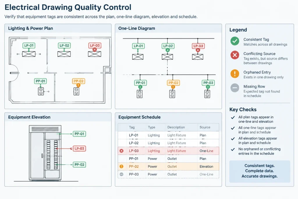
- Extract or list equipment tags: Collect tags from relevant plans, diagrams, elevations, and existing schedules.
- Normalize names: Find differences in spacing, punctuation, prefixes, and abbreviations.
- Check completeness: Identify plan symbols without schedule rows and schedule rows without drawing occurrences.
- Trace sources: Compare each documented source with the single-line, riser, panel, or feeder information.
- Verify locations: Reconcile schedule locations with current architectural backgrounds.
- Test references: Confirm that sheet, detail, and diagram references reach the intended view.
- Review technical fields: Mark unknown information for resolution instead of filling it by assumption.
- Plot and inspect: Check text size, wrapping, line hierarchy, blank cells, and continuation labels in the issued format.
Common Schedule Problems
- Orphaned rows: Equipment remains in the table after being removed from the drawings.
- Unscheduled symbols: A plan tag has no matching schedule entry.
- Conflicting sources: The schedule and single-line diagram identify different upstream equipment.
- Copied remarks: Notes carried from another row do not apply to the current item.
- Uncontrolled blanks: Empty cells do not indicate whether information is unknown, not applicable, or intentionally omitted.
- Excessive duplication: The same technical value appears in several places and is revised in only one.
- Unreadable formatting: Dense columns and reduced text make the schedule difficult to use when plotted.
Treat the Schedule as a Project Index
A strong equipment schedule gives readers a dependable path through the electrical documentation. It identifies equipment consistently, records selected coordination information, and points toward the plans, diagrams, details, and specifications that complete the design intent.
The schedule should be reviewed whenever equipment is added, removed, renamed, relocated, or reconnected. With a defined scope, stable tag system, disciplined CAD structure, and routine cross-checking, it becomes a practical coordination resource instead of another table that must be interpreted cautiously.
Schedule Governance and Revision Control
A schedule remains dependable only when the project team knows who controls each field. Equipment tags may be managed by the electrical discipline, while room names, equipment descriptions, connection information, or status designations may originate elsewhere. Identifying the controlling source helps prevent a copied schedule cell from being mistaken for current design information.
During revisions, review the schedule by change type rather than checking only the visibly edited row. A relocated item can affect its location, plan reference, detail reference, source relationship, and status. A renamed item can require updates on plans, diagrams, elevations, callouts, and schedules. Deleted equipment should be checked for remaining symbols, leaders, notes, and references.
Use Deliberate Placeholder Language
Blank cells are easy to misinterpret. Project drafting conventions should distinguish information that is unresolved from information that does not apply or is intentionally shown elsewhere. Placeholder language should be consistent, searchable, and removed or resolved before the applicable issue milestone.
Establish a Clear Information Hierarchy
When the same information appears in several documents, the team should identify which location controls it and which locations merely reference or summarize it. This reduces contradictory edits and makes quality-control review more efficient. The equipment schedule is usually most effective as an index and coordination surface, not as a replacement for diagrams, details, specifications, or manufacturer documentation.
Final CAD Review Questions
- Does every equipment tag follow the project naming convention?
- Can each scheduled item be found on the relevant plan or diagram?
- Do source and destination relationships agree across the drawing set?
- Are room names, area descriptions, and drawing references current?
- Are unresolved entries clearly identified rather than silently assumed?
- Can the schedule be read in the plotted deliverable without relying on CAD display settings?
- Will recipients be able to open and maintain the chosen table format?
A disciplined closeout review should compare the schedule with the issued drawing views rather than relying solely on the CAD model or an external data file. This confirms that the information readers receive is coordinated, visible, and traceable.
Frequently Asked Questions
What is an electrical equipment schedule in CAD?
It is a structured drawing table that identifies selected equipment and connects each item with relevant locations, sources, plans, diagrams, details, statuses, or remarks. Its exact scope should be defined for the project.
Is an equipment schedule the same as a panel schedule?
No. An equipment schedule generally indexes equipment and coordination references, while a panel schedule documents information associated with a particular panel and its circuits. The documents may reference one another, but they should not become conflicting copies of the same data.
Should every technical characteristic be included in the schedule?
Not necessarily. Include fields that support reliable coordination and can be maintained throughout the project. Detailed requirements may be better located in specifications, diagrams, details, or verified equipment documentation.
How should unknown schedule information be handled?
Do not fill an unknown field by assumption. Use the project’s approved method for identifying unresolved information, assign responsibility for verification, and review the entry before issue.
What should happen when an equipment tag changes?
Search the complete drawing set and associated project data for the previous identifier. Update plans, diagrams, details, schedules, callouts, and references together so the old and new tags do not coexist unintentionally.
Which CAD table method is best?
The best method is the one the project team and recipients can edit, exchange, plot, and quality-check reliably. Native tables, attributed blocks, linked data, and structured linework each have advantages and maintenance risks.









Leave a Reply
You must be logged in to post a comment.