
Architectural underlays for electrical CAD plans are more than visual backgrounds. They establish the spatial context for device placement, coordination, annotation, and sheet review, but they can also transmit unnoticed changes throughout an electrical drawing set.
This reference focuses on the documentation controls that make underlay updates easier to evaluate. It is intended for CAD drafters, designers, engineers, students, and reviewers who need to distinguish a genuine building revision from a file-alignment, reference-path, or display problem.
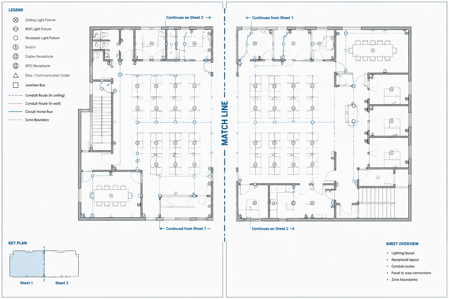
Architectural underlays provide the spatial framework for most electrical floor plans. Walls, doors, room names, ceilings, casework, and equipment locations help the electrical drafter place devices and communicate design intent. The same background can also become a major source of drawing errors when files move, coordinates change, layers multiply, or architectural revisions are incorporated without review.
A reliable workflow treats the underlay as controlled project information rather than passive linework. It should be traceable to a specific consultant issue, visually subordinate to electrical content, and replaceable without disturbing electrical geometry. This guide explains how to manage architectural underlays for electrical CAD plans from initial receipt through final drawing review.
What Is an Architectural Underlay?
An architectural underlay is a referenced or imported drawing used as the base for another discipline’s work. On an electrical plan, it may show building geometry, room organization, reflected ceiling information, furniture, casework, doors, and selected annotations.
The underlay is not automatically a complete or current representation of architectural scope. Its purpose depends on the electrical plan type. A power plan may need walls, doors, room names, equipment, and casework, while a lighting plan may rely more heavily on ceiling grids, ceiling features, and fixture coordination information.
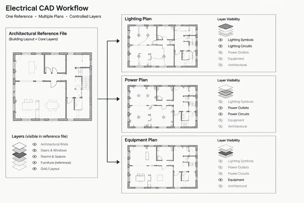
For that reason, one architectural background should not be assumed to serve every electrical sheet without adjustment. The source can remain common, but its layer visibility and display treatment may vary by viewport or plan type.
Reference the Source Instead of Copying It
Where the project workflow permits, attach the architectural file as an external reference rather than copying its geometry into the electrical model. A reference keeps architectural objects separate from electrical work and makes later replacement more manageable.
Copying background geometry into an electrical file creates several risks:
- Architectural and electrical objects can become indistinguishable.
- Duplicate walls, doors, and room labels may remain after updates.
- Background edits may be mistaken for electrical design changes.
- The electrical file can become unnecessarily complex.
- It becomes difficult to identify which architectural issue was used.
A referenced background does not eliminate coordination work. It simply creates a clearer boundary between source information and electrical documentation.
Establish a Controlled File Structure
Store received backgrounds in a defined project location rather than attaching files directly from an email folder, temporary download directory, or personal workspace. The project team should be able to identify the active background and the files that have been superseded.
A practical background register can record:
- Source discipline and file name
- Date received
- Consultant issue description
- Date incorporated into the electrical set
- Electrical sheets or models affected
- Name or initials of the reviewer
- Notes about known exclusions or coordinate changes
File names alone are not always reliable indicators of content. A newer-looking name may contain older geometry, and a consultant may reissue a file without visibly changing its name. A simple register provides traceability that the CAD reference manager cannot supply by itself.
Verify Alignment Before Drafting
Before placing or moving electrical symbols, confirm that the architectural file aligns with the established project coordinate system. Do not use a convenient wall corner as the sole test unless that point is an agreed project reference.
Check several widely separated and stable features, such as structural grid intersections, building corners, shaft boundaries, or other recognized control points. A file may appear aligned in one area while being rotated, shifted, or scaled incorrectly elsewhere.
Review these conditions when attaching a new underlay:
- Insertion point and coordinate relationship
- Drawing units
- Rotation
- Overall building alignment
- Floor-to-floor stacking where relevant
- Presence of nested references
- Unexpected clipping boundaries
If adjustment is necessary, document the reason and method. Repeatedly moving the reference by eye makes future updates unpredictable and can separate electrical symbols from their intended rooms or equipment.
Choose the Right Underlay Content for Each Plan
An effective electrical background contains enough information for orientation and coordination without competing with the electrical scope. More visible architectural information does not necessarily produce a better drawing.
| Electrical plan type | Commonly useful underlay content | Content often screened or hidden |
|---|---|---|
| Lighting plan | Walls, room names, ceiling layout, ceiling features, doors | Dense finish notes, dimensions unrelated to fixture placement, excessive furniture detail |
| Power plan | Walls, doors, room names, casework, equipment footprints, furniture where connection points depend on it | Ceiling annotation, finish patterns, decorative linework |
| Equipment layout | Room boundaries, access points, structural features, nearby equipment, service interfaces | Remote-area details and annotations unrelated to coordination |
| Roof electrical plan | Roof boundaries, equipment, curbs, access paths, major drainage and structural coordination features | Interior floor-plan information that does not affect roof work |
This selection should reflect project needs. It is not a substitute for reviewing the architectural documents or coordinating with the design team.
Control Appearance Without Editing the Source
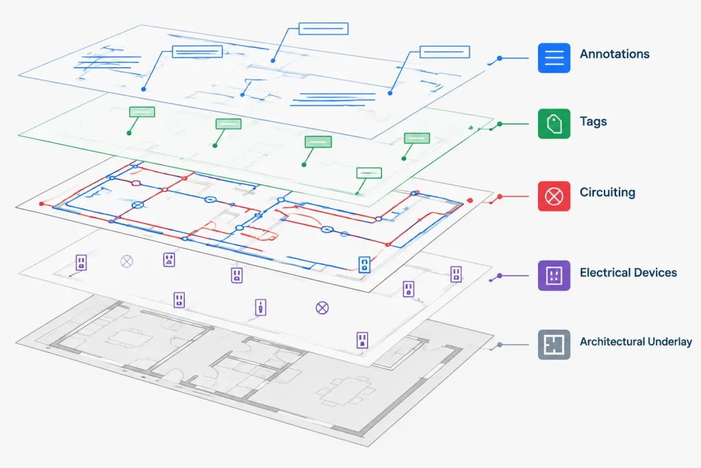
The architectural underlay should usually read as secondary information. Electrical devices, circuiting, tags, and notes should remain visually dominant when the sheet is plotted.
Control underlay appearance through reference layers, viewport overrides, plot styles, screening, or other project-approved display methods. Avoid opening the consultant’s file and changing its objects solely to improve the electrical plot. Local edits to a received source can be lost at the next update and may create uncertainty about whether the background still matches the architect’s issue.
Review the plotted result rather than relying only on model-space color. A background that looks subdued on screen may reproduce too dark in PDF or print. Conversely, excessive screening can erase door swings, room divisions, or casework that readers need to interpret device locations.
Replace Backgrounds Through a Deliberate Update Cycle
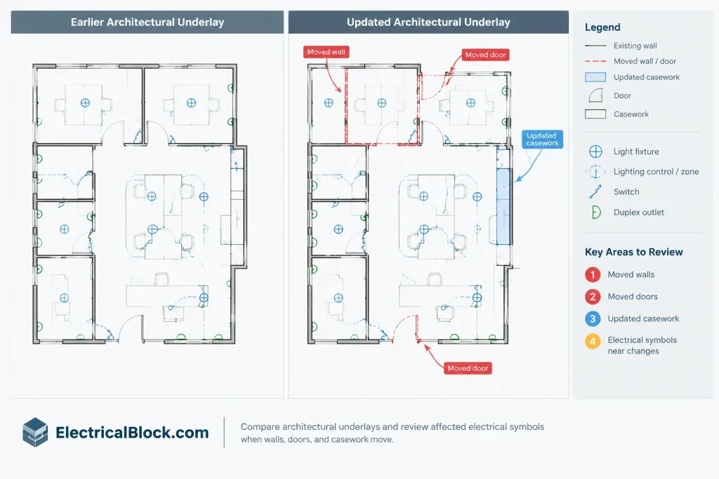
A new architectural issue should not be attached and accepted without comparison. First preserve or record the currently used issue, then load the replacement in a controlled review environment. Confirm alignment before evaluating design changes.
Separate file movement from design movement
If the entire building appears to shift, investigate coordinates, insertion settings, and source-file setup before moving electrical work. A global reference displacement is different from a genuine architectural revision.
Compare meaningful building features
Review changes to walls, doors, room boundaries, room identifiers, ceilings, casework, equipment, shafts, and other features that influence electrical documentation. Automated drawing comparison can help locate differences, but it cannot determine their electrical significance.
Review electrical consequences
For each relevant architectural change, check the associated electrical content. A moved door may affect a wall switch location. Revised casework may affect receptacle placement. A changed room boundary may affect circuit tags, occupancy-related controls, or sheet coverage. A renamed room may require updates across plans and schedules.
Record the review
Note which background was incorporated, which sheets were reviewed, and whether unresolved items remain. This creates an auditable handoff between the person updating the CAD files and the person responsible for design coordination.
Avoid Automatically Moving Electrical Objects
It can be tempting to move electrical symbols immediately when walls or furniture shift. First determine what the symbol represents and what controls its location.
A device shown near a wall may be dimensioned from a grid, coordinated with equipment, aligned with an elevation, or intentionally offset for readability. Moving it to follow underlay graphics could break another documented relationship.
Use the architectural change as a coordination prompt. Then review associated dimensions, leaders, circuits, home runs, tags, enlarged plans, details, and schedules before deciding what should move.
Manage Nested References and Unavailable Files
Architectural models often contain references to other files. Nested structural, landscape, interior, or consultant backgrounds may appear automatically, disappear when paths fail, or introduce layers that are irrelevant to the electrical set.
Inspect the reference hierarchy instead of assuming that every visible object belongs to the main architectural file. Confirm whether nested files are required, whether their paths are portable, and whether their visibility should be controlled independently.
Missing references should be treated as a documentation issue, not merely an on-screen warning. A plan can open and plot while lacking critical ceiling, equipment, or room information. Include reference-path verification in both drawing setup and file-handoff reviews.
Keep Electrical Content Independent
Electrical blocks, tags, dimensions, and circuiting should remain on electrical layers and should not be embedded in the architectural reference. Likewise, electrical annotations should not depend on architectural objects in ways that fail when the reference is replaced.
Where associative tools or object links are used, test how they behave after a background reload. Convenience during drafting should not create fragile documentation that changes unexpectedly when a consultant file is updated.
Underlay Review Checklist
- Confirm the source, receipt date, and issue description.
- Attach the file from the controlled project location.
- Verify units, insertion, rotation, and alignment at multiple control points.
- Inspect nested references and missing-file warnings.
- Apply plan-specific layer visibility and graphic treatment.
- Compare the replacement with the previously used background.
- Review walls, doors, rooms, ceilings, casework, and equipment changes.
- Check affected electrical symbols, tags, circuiting, notes, details, and schedules.
- Test the plotted PDF for hierarchy and legibility.
- Record the incorporated background and unresolved coordination items.
Make the Underlay Traceable, Subordinate, and Replaceable
A well-managed architectural underlay supports electrical drafting without becoming part of the electrical design geometry. It can be traced to a received issue, displayed with an appropriate graphic hierarchy, and replaced through a repeatable review process.
The main goal is not simply to keep references loaded. It is to understand what changed, identify which electrical documents are affected, and preserve confidence that symbols and annotations still correspond to the intended building layout. That discipline turns a background file into a dependable coordination resource rather than an uncontrolled source of drawing changes.
Classify Each Difference Before Revising the Electrical Plan
A productive update review separates detected differences into practical categories. This prevents the team from treating every changed line as an electrical design revision.
- Reference setup change: The apparent difference results from insertion, rotation, units, clipping, coordinates, or reference hierarchy.
- Graphic display change: Layer visibility, screening, plot behavior, or annotation density changed without altering the building layout.
- Architectural coordination change: A wall, door, ceiling feature, room, casework element, or equipment footprint changed in a way that may affect electrical documentation.
- Informational change: Names, notes, identifiers, or other descriptive content changed and may need to be reconciled with electrical tags, schedules, or references.
- Unresolved change: The electrical consequence cannot be determined from the received files and requires clarification.
Recording the category beside each significant difference gives reviewers a clearer basis for deciding whether electrical geometry, annotation, or related documentation should be revised.
Use a Sheet-Impact Review Instead of an Isolated Plan Check
An architectural change may extend beyond the sheet where it was first noticed. Before closing the update, identify the electrical documents that depend on the changed area or room information.
- Floor plans and reflected ceiling coordination views
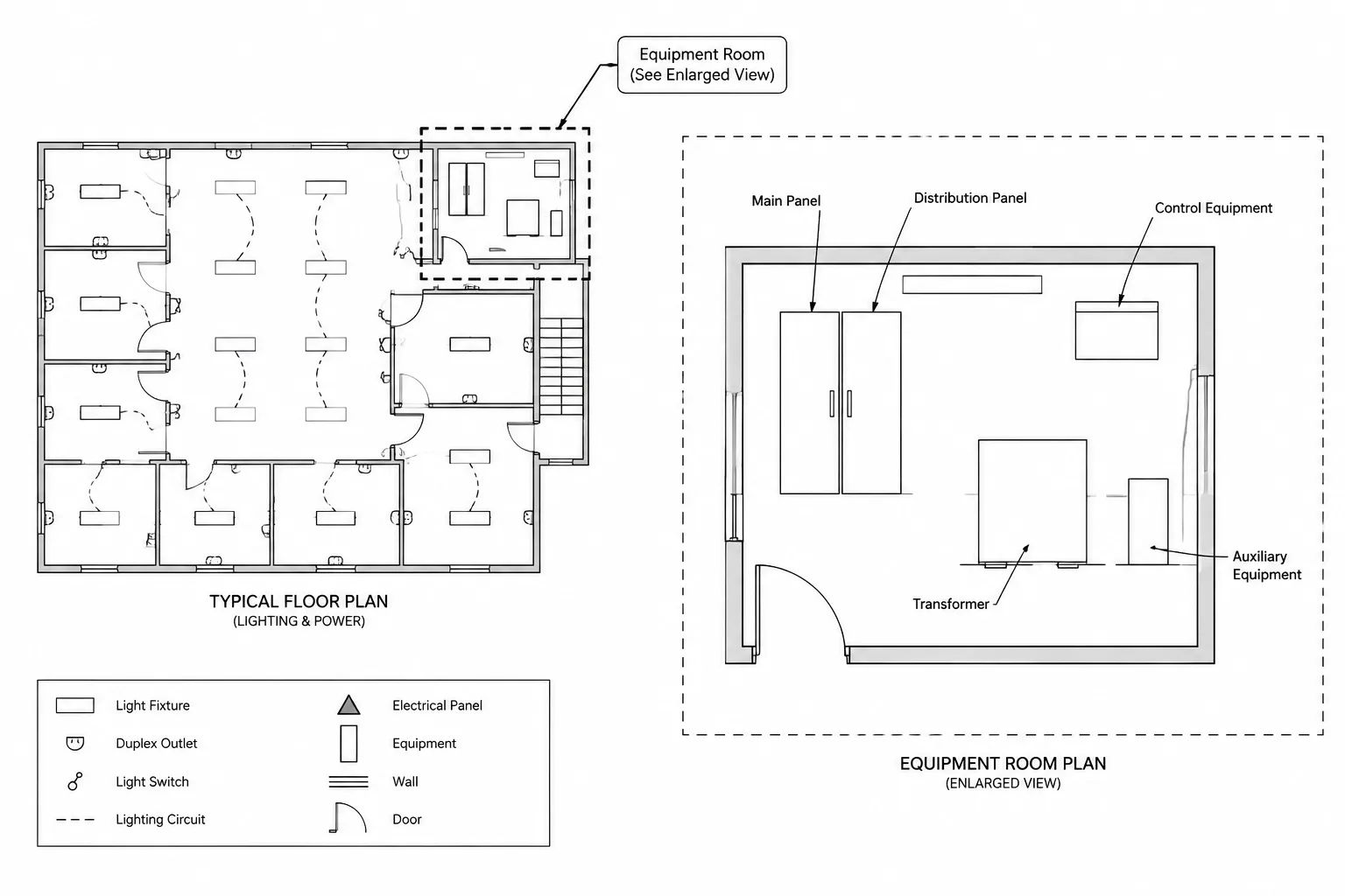
- Enlarged plans, details, and equipment layouts
- Device tags, circuit annotations, and home-run graphics
- Room-based notes, schedules, legends, and keyed references
- Match lines, view boundaries, and cross-sheet callouts
This dependency review is especially useful when the CAD model and published sheets do not share identical layer states or viewport extents. A change can be present in the model while remaining hidden, clipped, or visually obscured on a plotted sheet.
Define a Clear Completion State
An underlay update should not be considered complete merely because the replacement file loads without errors. Completion means that the source has been identified, alignment has been verified, relevant differences have been reviewed, affected electrical documents have been checked, and unresolved items have been recorded for follow-up.
That definition creates a consistent handoff between file management, drafting, design coordination, and quality review. It also reduces the risk that a visually successful reload will be mistaken for a fully coordinated update.
Frequently Asked Questions
Should an architectural underlay be bound into the electrical drawing?
Binding may be required for a particular archive or file-delivery workflow, but it should not replace controlled reference management during active drafting. Keeping the source referenced generally makes its origin, visibility, and replacement easier to manage. Any binding step should follow the project’s documented handoff requirements.
Why can an underlay look aligned in one location but be wrong elsewhere?
A local match can conceal a rotation, scale, unit, or coordinate problem. Alignment should be checked against multiple stable project control features that are widely separated rather than against a single convenient wall corner.
Should electrical symbols move whenever an architectural wall moves?
No. The wall change should trigger a coordination review, not an automatic symbol move. The device may also relate to equipment, casework, a ceiling feature, a grid, an elevation, or another documented control.
Can the same architectural layer display be used for every electrical plan?
Not necessarily. Lighting, power, equipment, and roof plans use different architectural context. Viewport overrides, layer states, or other approved display controls can tailor the same source reference without duplicating its geometry.
What should be checked when a replacement underlay appears blank or incomplete?
Review the reference path, layer visibility, clipping, nested references, coordinate location, and viewport settings. A file may be loaded correctly while its useful content is hidden, displaced, clipped, or dependent on an unavailable nested source.
How should unresolved architectural changes be handled in the CAD record?
Keep the received issue traceable, identify the affected drawing area, and record the question or coordination dependency. Avoid making an undocumented assumption that could be mistaken for confirmed design information later.









Leave a Reply
You must be logged in to post a comment.