
Electrical CAD xrefs connect electrical plans to architectural, structural, civil, and equipment-layout backgrounds while allowing each discipline to maintain its own drawing files. Their value depends on more than whether a reference loads: nesting behavior, path selection, coordinate alignment, layer visibility, and revision control all affect the reliability of the drawing set.
This reference explains how attachment and overlay choices influence downstream files, how path strategies affect portability, and how controlled background updates support multidisciplinary coordination. Use it as a drafting and document-management guide, then apply the naming, storage, and issue procedures established for the project.
External references, commonly called xrefs, allow an electrical drawing to display information stored in another CAD file without copying that geometry into the active drawing. Electrical teams routinely use xrefs for architectural floor plans, reflected ceiling plans, structural backgrounds, civil site plans, equipment layouts, and drawings produced by other disciplines.
An effective xref workflow does more than place a background on screen. It controls which files appear, how nested references behave, whether file locations remain valid, and how consultant updates are reviewed. Poor xref management can result in missing backgrounds, duplicated geometry, unexpected plotting, and electrical symbols that no longer align with the building layout.
The exact commands and terminology vary among CAD platforms, but the following principles apply broadly to reference-based electrical drafting.
What an Xref Does in an Electrical Drawing
An xref links the current drawing to a separate file. The referenced geometry remains in its source file while being displayed within the host electrical drawing. When the source file is revised and the reference is reloaded, the host drawing displays the updated information.
This separation is useful because the electrical team can maintain its own design files while the architect or another consultant maintains the background. It also avoids turning every electrical plan into a collection of copied architectural lines.
An xref should not be treated as an electrical block library item. A block usually represents reusable content managed within a drawing or library, while an xref normally represents a separate drawing file that must retain an independent identity and update path.
Attachment Versus Overlay
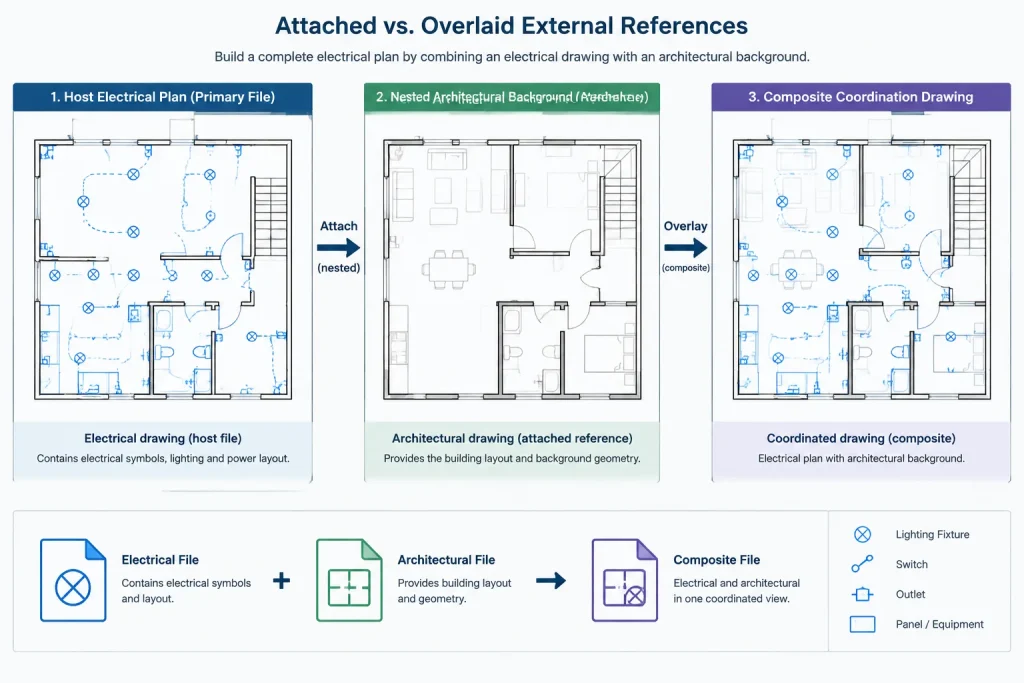
Many CAD systems provide two common ways to reference a drawing: attachment and overlay. The difference becomes important when references are nested.
| Reference type | Typical behavior | Common electrical use |
|---|---|---|
| Attachment | The referenced file can remain visible when the host drawing is referenced into another drawing. | Used when downstream drawings must receive both the host file and its nested reference. |
| Overlay | The reference appears in the current host but does not continue through another level of nesting. | Often used for consultant backgrounds to prevent duplicate architectural or structural files. |
For example, an electrical lighting file may reference an architectural reflected ceiling plan. If the lighting file is later referenced into a coordination sheet, an attached ceiling plan may travel with it. An overlaid ceiling plan generally stops at the lighting file. This can help prevent the same architectural background from appearing several times through different consultant files.
Overlay is therefore a common choice for coordination backgrounds, but it is not automatically correct for every workflow. The project team should decide which nested information must remain visible in composite drawings before selecting the reference type.
Establish a Predictable File Structure
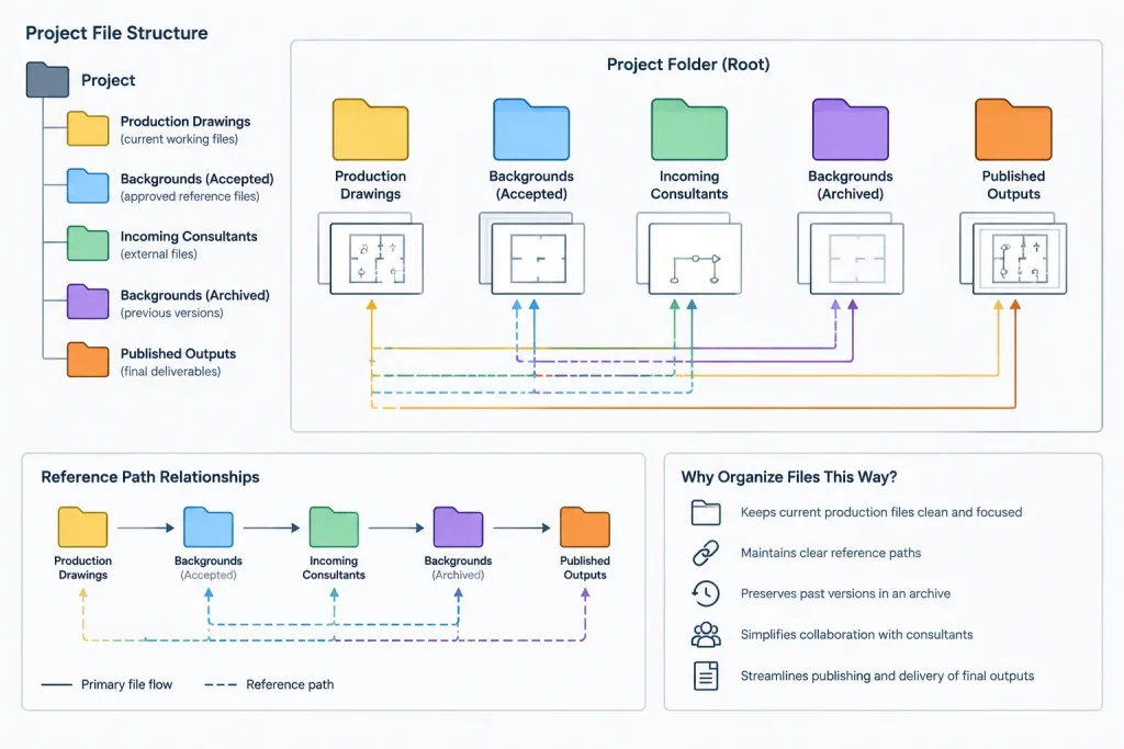
Xref reliability depends heavily on file organization. Moving or renaming a source drawing without updating its reference path can create a missing-file condition. A controlled project folder structure makes drawing transfers, archiving, and consultant exchanges easier to manage.
A practical structure may separate:
- Current electrical drawing files
- Current consultant backgrounds
- Superseded or archived backgrounds
- Published PDF or plot outputs
- Incoming files that have not yet been reviewed
- Temporary coordination or comparison files
Incoming files should not automatically replace production backgrounds. First confirm the file identity, drawing units, insertion basis, orientation, and revision scope. After review, move or copy the accepted file into the controlled background location according to the project’s document-management procedure.
Choose File Paths for the Handoff Method
A reference path tells the host drawing where to find its source file. CAD applications commonly support path approaches such as full, relative, or unresolved/no-path references, although available options and names differ.
Full paths
A full path records a specific storage location. It can be dependable within a fixed office environment but may fail when the project is moved to another server, workstation, or delivery folder.
Relative paths
A relative path describes the source file’s location in relation to the host drawing or project structure. This approach can improve portability when the entire folder structure is transferred intact.
No-path or search-based references
A drawing may rely on the source file being in the same folder or in a configured search location. This can simplify some deliveries, but identical filenames or inconsistent search settings may cause the wrong background to load.
Select the path method based on how the project will be stored, shared, and archived. A path that works for one drafter is not sufficient if it fails for reviewers, consultants, or the final recipient.
Verify Position, Units, and Orientation
An xref that loads successfully can still be incorrect. Before drafting against a new background, verify that it aligns with the project coordinate system and intended plan orientation.
Review the following:
- The xref insertion point and drawing origin
- The displayed scale and source drawing units
- Rotation relative to the electrical sheet and other disciplines
- Alignment at grids, columns, walls, and other stable control points
- Vertical or floor-level identity where similar plans exist
- Whether the background has been moved merely to fit a sheet
A consultant background should generally remain aligned to agreed project coordinates. Sheet composition is better handled with viewports, clipping boundaries, and sheet layout controls than by moving the source geometry into a visually convenient but uncoordinated position.
Control Xref Layers Without Editing the Source
Referenced drawings frequently contain more information than an electrical plan needs. Furniture, room finishes, ceiling patterns, dimensions, survey data, or consultant annotations may compete with electrical symbols and circuiting.
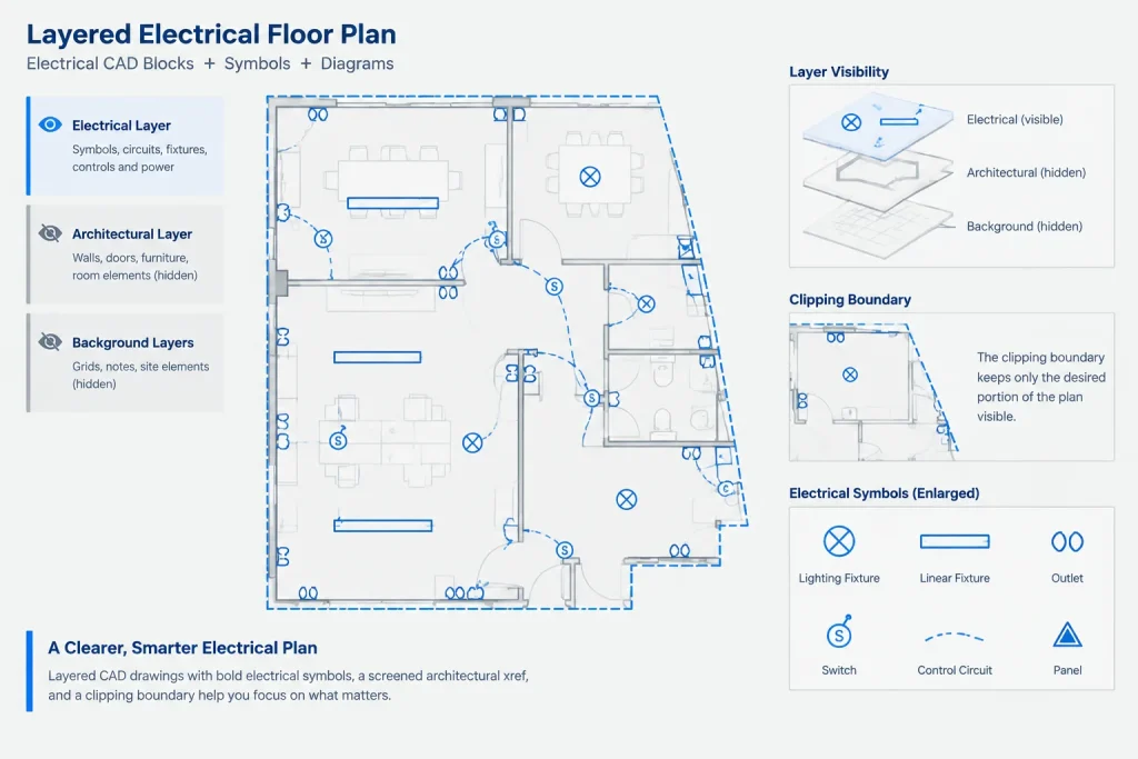
Use host-drawing layer controls to adjust the reference’s visibility and graphic weight where the workflow permits. Common actions include:
- Turning off layers unrelated to electrical coordination
- Screening background linework for plotting
- Reducing the prominence of dense hatches
- Keeping grids, room names, walls, and major equipment visible
- Creating viewport-specific visibility for different plan types
A lighting plan and a power plan may use the same architectural source while displaying different background layers. Avoid deleting or permanently changing source content simply to improve one electrical sheet. If a background requires cleanup, document whether the adjustment belongs in the source file, an agreed intermediate file, or the electrical host drawing.
Use Clipping Boundaries Carefully
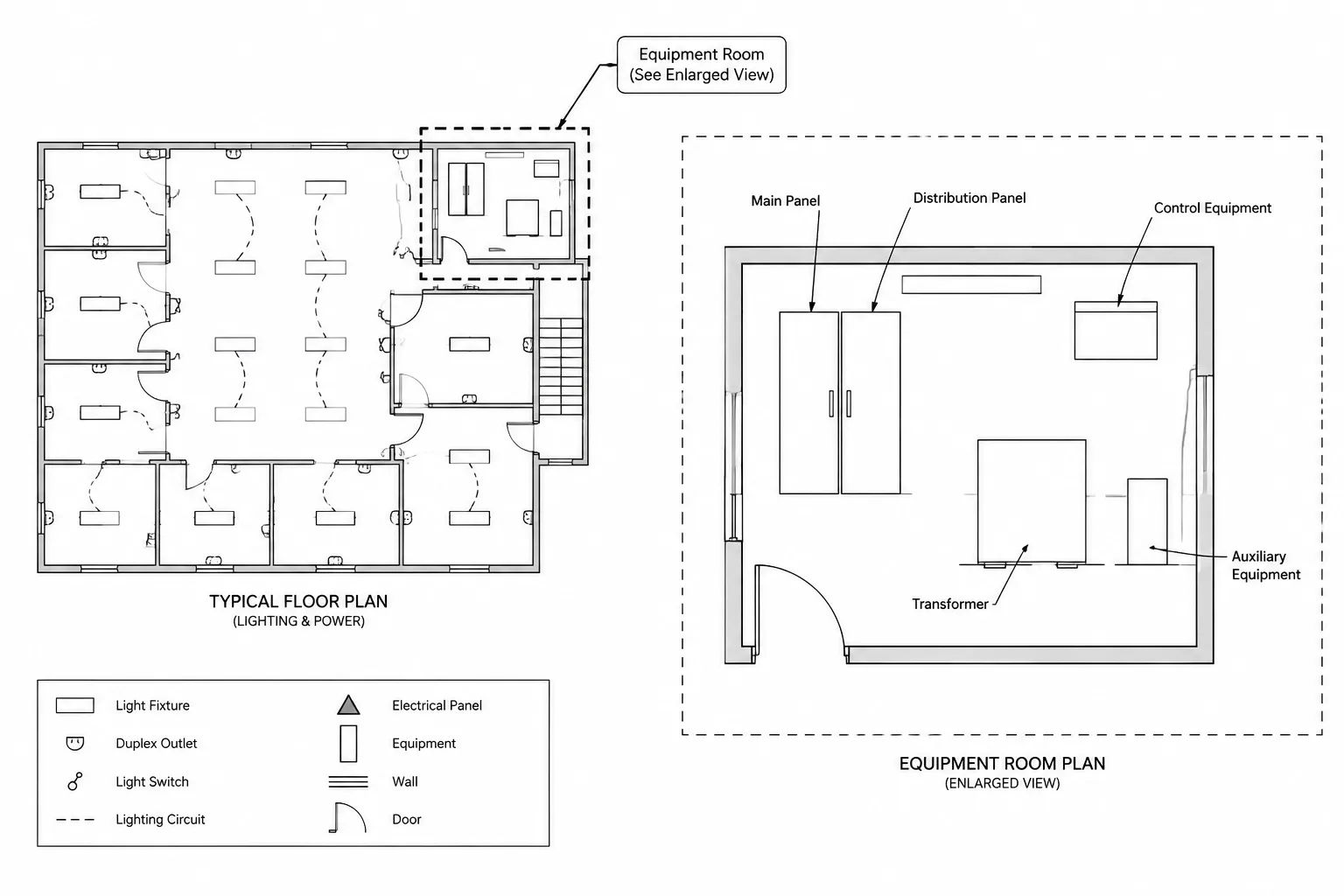
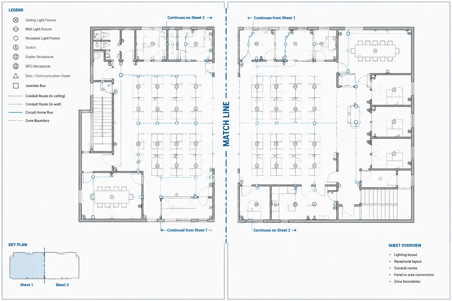
An xref clipping boundary can limit the displayed portion of a larger reference. This is useful for partial plans, enlarged areas, campus buildings, and floor files that extend beyond the electrical sheet.
Clipping should support sheet organization without hiding coordination information. Leave enough surrounding context to show access routes, adjacent rooms, grid references, and continuation points. When a floor is divided among sheets, coordinate clipping boundaries with match lines, key plans, and cross-references.
Review clipping after each major background update. A changed building footprint or shifted plan area may leave valid geometry outside an older clipping boundary.
Manage Background Updates as Controlled Revisions
Reloading a revised xref can change the apparent electrical design even when no electrical entities were edited. Walls may move, room names may change, ceiling grids may be revised, or equipment supplied by another discipline may shift.
A controlled update workflow should include:
-
Record the filename, received date, and source of the incoming background.
-
Retain the previous accepted background according to the project archive procedure.
-
Compare the incoming file with the previous version.
-
Review coordinate, unit, and orientation consistency before replacement.
-
Reload the reference in affected electrical drawings.
-
Inspect device positions, circuiting, notes, dimensions, and callouts near changed areas.
-
Document resulting electrical revisions through the project’s issue-control process.
Do not assume that an unchanged filename means unchanged content. Likewise, a filename change does not necessarily mean the geometry has changed. Comparison and visual review provide better evidence than naming alone.
Avoid Binding References Too Early
Binding or otherwise converting an xref into local drawing content can be useful for a required deliverable, archive, or disconnected handoff. However, it also breaks the normal live relationship with the source file and may introduce layers, blocks, and naming conflicts into the host drawing.
Keep live references during active coordination unless the project workflow requires another approach. If a bound package is needed, create it from a controlled copy and verify the result independently. The editable production file should not lose its coordinated reference structure merely to create a one-time transmission.
Pre-Issue Xref Checklist
- Confirm that every required reference is found and loaded.
- Check that no obsolete or unintended references are attached.
- Review nested xrefs for duplicate backgrounds.
- Confirm reference type, path, scale, rotation, and insertion point.
- Verify layer visibility in every plotted viewport.
- Inspect clipping boundaries and partial-plan limits.
- Make sure the latest accepted consultant files are being used.
- Plot or publish a review set and inspect background readability.
- Test the drawing package in its intended delivery folder.
- Document any references intentionally excluded from the handoff.
Treat Xrefs as Part of the Drawing Record
Electrical CAD xrefs are not merely background display tools. They are dependencies that influence coordination, plotting, revision review, and long-term access to the drawing set. Clear folder rules, deliberate attachment choices, stable coordinates, and documented updates help the electrical drawings remain understandable when files move between users and organizations.
Before relying on any referenced drawing for a real project, verify its source, revision status, units, coordinates, and intended use. A technically clean reference structure supports drafting efficiency, but it does not replace project-specific design review or multidisciplinary coordination.
A Practical Decision Framework for Xrefs
Before adding a reference, identify its purpose in the host drawing. A background needed only for local coordination may require different nesting behavior from a file that must remain visible in a composite drawing. The intended handoff method should also influence the path choice and folder structure.
Separate display decisions from dependency decisions
Layer visibility, screening, and clipping control how a reference appears. Attachment type, file path, and nesting control how the dependency behaves. Treating these as separate decisions makes troubleshooting easier because a reference can be correctly located but poorly displayed, or visually correct while still relying on an unstable file path.
Check identity before alignment
A background can align perfectly and still be the wrong floor, area, discipline, or revision. Confirm the file identity and acceptance status before using grids, walls, or other control points to evaluate alignment.
Review the electrical consequences of every update
An xref update is not merely an architectural change. Revised rooms, ceilings, walls, and equipment locations can affect electrical symbols, circuit graphics, notes, dimensions, and sheet composition. Comparison results should therefore lead to a focused review of the electrical information near each changed area.
Common Xref Symptoms and Likely Causes
- The reference is missing: Review the stored path, filename, folder access, and delivery structure.
- The background appears more than once: Inspect nested attachments and determine whether an overlay should stop the reference from propagating.
- Electrical symbols no longer align: Check the accepted background revision, insertion basis, units, rotation, and project coordinates.
- The reference loads but does not plot as expected: Review xref layer settings, viewport overrides, clipping, plot controls, and frozen or disabled layers.
- Another user sees a different file: Check for duplicate filenames, search-path differences, or local copies outside the controlled project structure.
- A revised area is not visible: Inspect clipping boundaries and confirm that the correct source file was reloaded.
Resolve the dependency or display cause rather than compensating by moving electrical geometry. Local visual corrections can conceal an underlying coordination problem and make later updates harder to evaluate.
Frequently Asked Questions About Electrical CAD Xrefs
Should an architectural background be attached or overlaid?
Overlay is often useful when the background should appear only in the current electrical host and should not continue through nested references. Attachment is appropriate when downstream drawings must receive the host and its referenced content. The correct choice depends on the project’s composite-drawing and delivery workflow.
Why does an xref work on one workstation but not another?
The host drawing may rely on a storage location, search path, drive mapping, or local folder that is unavailable elsewhere. Review the stored reference path and test the complete package from the folder structure intended for sharing or delivery.
Can xref layers be hidden without editing the consultant file?
Many CAD workflows allow the host drawing to control the visibility and appearance of referenced layers. This lets electrical sheets suppress unnecessary background information while preserving the consultant’s source file. Confirm how those settings are retained and plotted in the CAD platform being used.
Should an xref be moved to make it fit the electrical sheet?
Moving a coordinated background for sheet convenience can break alignment with other disciplines. Keep the reference on the agreed project basis where possible, and use viewports, clipping, and layout controls to compose the sheet.
When should an xref be bound?
Binding may be required for a specific archive or disconnected handoff, but it ends the normal live-reference relationship and can introduce naming conflicts or unwanted local content. Create bound deliverables from a controlled copy when the project procedure calls for them, and retain the coordinated production structure separately.
Does reloading an xref complete the coordination review?
No. Reloading only updates what the host displays. The electrical team still needs to identify relevant background changes and inspect affected symbols, circuiting, annotations, dimensions, and sheet limits.









Leave a Reply
You must be logged in to post a comment.