
Electrical demolition plans in CAD must preserve the relationship between existing systems, removal scope, and proposed construction. Effective documents make each item’s status visible while preventing unverified field assumptions from becoming apparent design facts.
This reference focuses on the drafting decisions that support readable demolition documents: controlled backgrounds, status-based graphics, coordinated circuit information, disciplined notes, and review across plans, schedules, and diagrams.
Electrical demolition plans translate existing conditions and renovation scope into a drawing that contractors, reviewers, and other disciplines can interpret consistently. They are not simply copies of new-work plans with a few devices crossed out. A useful demolition plan distinguishes what exists, what will be removed, what will remain, and what may need temporary protection or relocation.
Because demolition documents depend heavily on field information, CAD drafting must also communicate uncertainty. Existing drawings may be incomplete, circuit records may be outdated, and concealed pathways may not be visible during design. The goal is to document known scope clearly while identifying items that require field verification rather than presenting assumptions as confirmed facts.
What an electrical demolition plan should communicate
A demolition plan should answer several practical questions without forcing the reader to infer scope from the proposed plan:
- Which electrical devices, fixtures, equipment, raceways, and connections are affected?
- Which existing items remain in service?
- Which items are removed completely, disconnected, relocated, or temporarily retained?
- Where does the demolition scope stop?
- Are existing circuits or systems serving areas outside the work zone?
- Which information must be verified in the field?
- Where can related panel, diagram, schedule, or detail information be found?
The drawings should describe documentation intent, not prescribe unsafe field procedures. Isolation, testing, sequencing, and work on electrical systems must be handled by qualified project participants under the applicable project requirements.
Start with a controlled existing-condition background
Begin with the best available architectural and electrical backgrounds. Record their source and date within the project file-management system. Avoid treating an old record drawing as a verified survey merely because it is available in DWG format.
Clean the background enough to make the demolition scope readable, but preserve information that may affect interpretation. Walls, room names, doors, ceiling features, equipment footprints, and major structural elements can all help locate electrical work. Excessive furniture, hatch patterns, consultant notes, or duplicated geometry may be screened, frozen, or removed from the working view according to the project workflow.
Keep referenced backgrounds separate from authored electrical demolition geometry. This makes later architectural updates easier to compare and reduces the risk of accidentally editing another discipline’s information.

Define status before choosing graphics
Every symbol and line should have a clear status. Establish the status categories before drafting so that graphic treatment remains consistent across plans, details, schedules, and diagrams.
| Status | Drawing meaning | Typical documentation approach |
|---|---|---|
| Existing to remain | An existing item is not included in the removal scope. | Show with a subdued but readable existing-condition style. |
| Remove | The item is included in demolition scope. | Use the project demolition linetype, symbol treatment, note, or tag. |
| Relocate | An existing item is removed from one location and installed elsewhere. | Reference both the demolition location and the proposed location. |
| Existing to remain temporarily | The item must be retained for a defined phase or temporary condition. | Add a phase or sequencing reference rather than relying only on linework. |
| Abandoned or inactive | The item is known or believed to be out of service. | Describe its documented status carefully and indicate required verification. |
| Unknown or field verify | Available records do not confirm the condition. | Use a specific verification note or keyed callout. |
Do not use “existing,” “abandoned,” and “remove” interchangeably. An item can be existing and active, existing and inactive, or existing and scheduled for removal. Precise wording prevents contradictory interpretations.
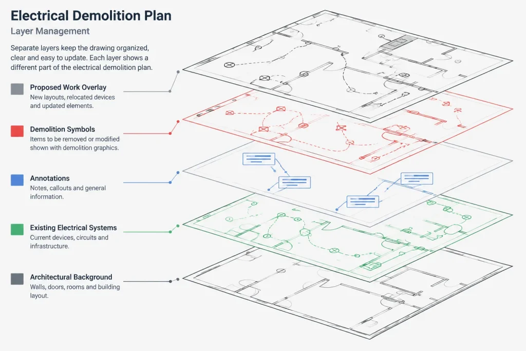
Build a demolition-specific layer structure
Demolition information should be separable from proposed work and background geometry. The exact layer names will depend on office or client standards, but the layer structure should support status filtering and reliable plotting.
Useful categories may include demolition devices, lighting, equipment, raceways, circuiting, text, tags, limits of work, and reference geometry. If the project uses color-based or named plot styles, test the demolition appearance in the final plotted format rather than judging it only from model-space colors.
Avoid putting every demolished object on one generic layer. Discipline or system separation makes it easier to isolate lighting, power, communications, life-safety interfaces, and other scopes during review. It also helps when different systems are issued or coordinated separately.
Choose a graphic convention that survives plotting
Demolition scope is often shown with dashed linework, strike-through marks, removal symbols, screening, or combinations of these methods. No single convention works for every project. The selected method must remain understandable in monochrome output, reduced-size prints, and rasterized review files.
Do not depend on color alone. A reviewer may receive a black-and-white print or view the sheet with altered display settings. Pair color with linetype, lineweight, notation, tags, or a clearly written legend.
Use strike-through graphics selectively
A diagonal slash or cross can make a device removal obvious, but dense strike-through marks can obscure the original symbol and nearby architecture. Use a consistent block or line style, maintain legibility, and avoid making the mark look like ordinary circuiting.
Keep demolition limits unambiguous
A limit-of-work boundary can help define the renovation area, but it does not automatically mean that every electrical item inside the boundary is removed. Pair the boundary with status graphics and notes. Conversely, show affected items outside the primary work area when their circuits, controls, or connections are part of the scope.
Document devices, circuiting, and upstream relationships
Removing a visible device may affect concealed wiring, shared circuits, control components, or downstream loads. The CAD plan should provide enough reference information for design coordination without claiming knowledge that has not been verified.
Where existing circuit information is reliable, coordinate device tags with panel schedules and diagrams. Where it is uncertain, state that the source or circuit requires field verification. Avoid assigning a panel or circuit merely to fill an empty tag.
When a circuit continues to serve equipment outside the demolition area, show the continuity requirement clearly. A note such as “remove device; maintain circuit continuity to remaining loads” may communicate intent better than deleting the device symbol and circuit line. The final wording should be reviewed for the particular project and system.
For equipment represented on a single-line or riser diagram, coordinate its demolition status in both locations. A plan showing equipment removal while the diagram still presents it as active creates a significant documentation conflict.
Coordinate demolition and proposed-work plans
Relocated devices are a frequent source of duplication. A device may appear as removed on the demolition plan and as new or relocated on the proposed plan. Use a shared identifier or clear cross-reference so reviewers can recognize that both symbols describe the same scope.
Compare the demolition and proposed plans side by side. Look for:

- Removed devices that reappear without a relocation reference.
- New walls that cover existing devices not addressed in demolition.
- Existing-to-remain equipment missing from the proposed background.
- Circuits shown removed on one sheet but reused on another.
- Lighting controls that remain after associated fixtures are removed.
- Equipment removed from plans but retained in schedules or diagrams.
- Notes that conflict with status graphics.
Demolition scope should also be checked against architectural demolition plans, reflected ceiling plans, mechanical equipment changes, furniture plans, and technology or fire alarm documents where those interfaces apply.
Use notes for intent, not as a substitute for drafting
General demolition notes can establish broad expectations, but a blanket note should not replace object-specific information. Statements such as “remove electrical as required” leave the affected items and scope boundaries open to interpretation.
Use keyed notes when several conditions share the same instruction. Keep each keynote focused on a single recognizable condition, and place the marker near the relevant object. If a note applies to an entire room or area, define that area graphically.
Notes should distinguish between confirmed information and required verification. Avoid language that implies a concealed raceway route, source, or service condition has been verified when it has only been inferred from incomplete records.
Create a practical CAD review sequence
- Freeze proposed work. Review the demolition plan as a standalone document and confirm that its scope is understandable.
- Isolate each system. Check lighting, power, controls, communications, and other applicable categories separately.
- Overlay proposed work. Look for relocated items, reused circuits, and conflicts with new construction.
- Review related documents. Compare plans with schedules, single-line diagrams, risers, details, and equipment lists.
- Test the plot. Confirm that existing, removed, and new conditions remain distinct in the actual issue format.
- Check references. Verify sheet numbers, detail callouts, keynotes, room names, and equipment identifiers.
- Record unresolved conditions. Add controlled verification notes or issue-tracking items instead of silently guessing.
Common drafting mistakes
- Erasing removed items instead of showing what is being demolished.
- Using color as the only status indicator.
- Showing every object within a demolition boundary as removed.
- Leaving demolished equipment active on a single-line diagram or schedule.
- Calling an unverified item abandoned.
- Mixing demolition and new-work geometry on layers that cannot be isolated.
- Using broad notes where a specific symbol, tag, or boundary is needed.
- Failing to address circuits that serve remaining loads.
- Allowing architectural background updates to erase or shift authored demolition information.
Final documentation principle
A strong electrical demolition plan does more than identify objects for removal. It explains status, preserves relationships to remaining systems, identifies uncertain information, and coordinates the transition from existing conditions to proposed work. Clear layer separation, consistent graphics, disciplined notes, and cross-sheet review make the CAD file more useful throughout design and construction documentation.
Before issue, project-specific scope, field conditions, drawing conventions, and applicable requirements should be reviewed by the responsible design professionals. CAD symbols and graphic conventions communicate intent, but they do not independently verify existing conditions or establish suitability for a particular installation.
Managing demolition-plan revisions
Demolition scope often changes as surveys, owner records, architectural backgrounds, and proposed layouts develop. Revision control should make it possible to identify what changed without losing the basis of the earlier drawing.
When updated information arrives, compare it with the current CAD background before replacing references. Review shifts in walls, room names, equipment footprints, ceiling features, and work boundaries. A background update can move authored demolition symbols away from the objects they were intended to identify even when no electrical geometry was deliberately edited.
Keep uncertainty traceable
A field-verification note should remain associated with the relevant object or area until the question is resolved. When verified information becomes available, update the affected plan graphics, notes, schedules, and diagrams together. Removing the note without correcting related documents can leave conflicting interpretations in the issue set.
- Record the source of updated existing-condition information.
- Review affected status tags and keyed notes.
- Check relocated items against the proposed-work plan.
- Confirm that schedule and diagram status matches the plan.
- Recheck plotting after layer, linetype, or reference changes.
Preparing the CAD file for handoff
A clear plotted sheet can still be difficult to maintain if demolition objects, reference files, and proposed work are not organized consistently. Before handoff, confirm that authored demolition geometry can be isolated, referenced backgrounds remain identifiable, and status conventions do not depend on a drafter’s personal display settings.
Reviewers should also be able to distinguish confirmed scope from coordination notes and unresolved conditions. This distinction supports better issue tracking and helps prevent preliminary assumptions from being carried forward as verified existing conditions.
Frequently asked questions
What is the difference between an electrical demolition plan and a proposed-work plan?
The demolition plan documents the transition from existing conditions by identifying items that remain, are removed, are relocated, or require verification. The proposed-work plan shows the intended resulting installation. The documents should be coordinated, but one should not be treated as a substitute for the other.
Should removed electrical symbols be deleted from the CAD plan?
No. Deleting them can erase the visual record of what is included in the removal scope. Retain the relevant symbol or geometry and apply the project’s demolition convention so the existing item and its intended status remain understandable.
Can a limit-of-work boundary define all demolition scope?
A boundary identifies an area of work, but it does not necessarily establish the status of every object within it. Individual graphics, tags, and notes should clarify which items remain and which are affected. Related circuits or equipment outside the boundary may also require documentation.
How should unknown existing circuit information be shown?
Use a controlled field-verification note or keyed callout rather than assigning an unsupported panel, circuit, or source. When the information is resolved, coordinate the correction across the plan, schedule, diagram, and related notes.
Why should demolition graphics be tested in the final plot format?
Model-space colors and display settings may not match printed or rasterized output. Plot review confirms that existing-to-remain and removal scope can still be distinguished through linetype, lineweight, symbols, tags, and notes without relying only on color.












Leave a Reply
You must be logged in to post a comment.