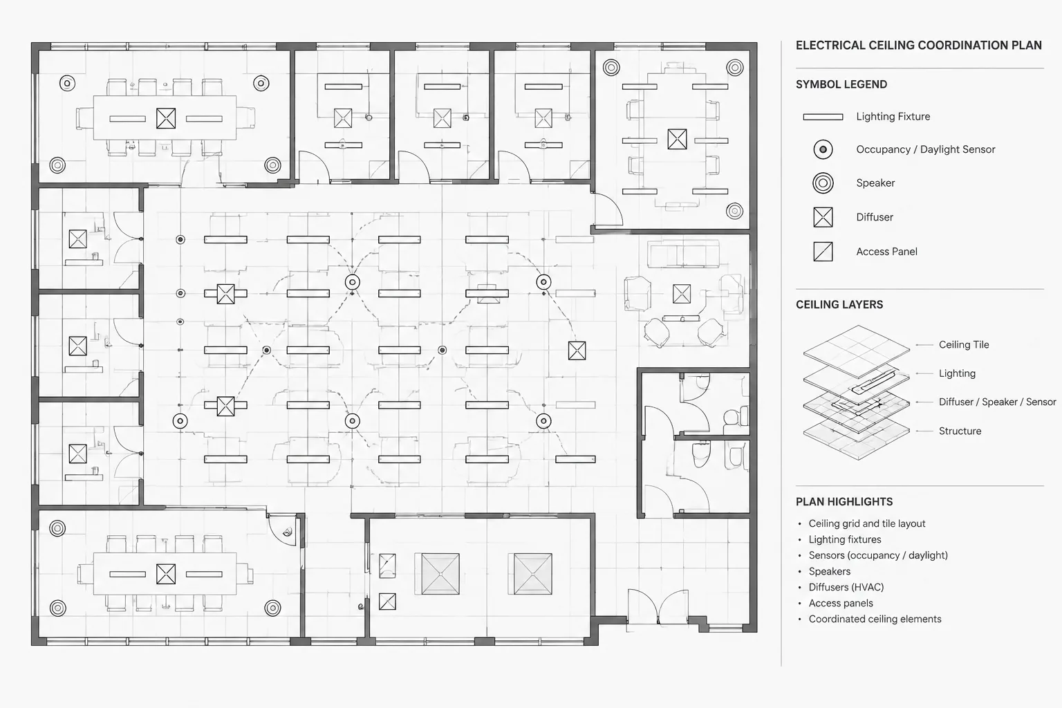
Ceiling coordination is a documentation task as much as a device-placement task. A useful CAD plan must bring several systems into one readable view while preserving the source, status, and ownership of each item. The guidance below explains how to manage backgrounds, symbols, layers, alignment references, conflict review, and drawing handoffs without confusing a coordination overlay with the discipline-specific design documents.
An electrical ceiling coordination plan brings ceiling-mounted electrical devices into a common drafting view so their locations can be checked against the reflected ceiling plan, architectural features, and other building systems. It is not simply another lighting plan. Its purpose is to expose spatial conflicts, unclear placement, and alignment problems before the drawing set is issued.
Lighting fixtures may share a ceiling with occupancy sensors, smoke detection devices, speakers, wireless access points, cameras, projectors, signage, diffusers, access panels, sprinklers, and structural elements. These items often originate in different models, CAD files, or design disciplines. A coordinated ceiling drawing helps the project team understand how they fit together without implying that one discipline has designed every system shown.
What an Electrical Ceiling Coordination Plan Shows
The plan typically uses the architectural reflected ceiling plan as its primary background. Electrical and related devices are overlaid in their intended plan locations, with enough supporting information to evaluate spacing, alignment, and conflicts.
Depending on the project scope, the drawing may include:
- Recessed, surface-mounted, suspended, and decorative lighting fixtures
- Emergency lighting units and exit signs
- Lighting control sensors and ceiling-mounted control devices
- Fire alarm notification and detection devices
- Speakers, paging devices, cameras, and wireless access points
- Ceiling-mounted receptacles or connection points for equipment
- Projectors, motorized screens, and audiovisual connection locations
- Ceiling grids, soffits, bulkheads, clouds, exposed structure, and access panels
- Selected mechanical and fire protection elements needed for coordination
Showing an item for coordination does not automatically assign design responsibility. The drawing should distinguish electrical scope from reference information supplied by other disciplines.
Coordination Plan Versus Lighting Plan
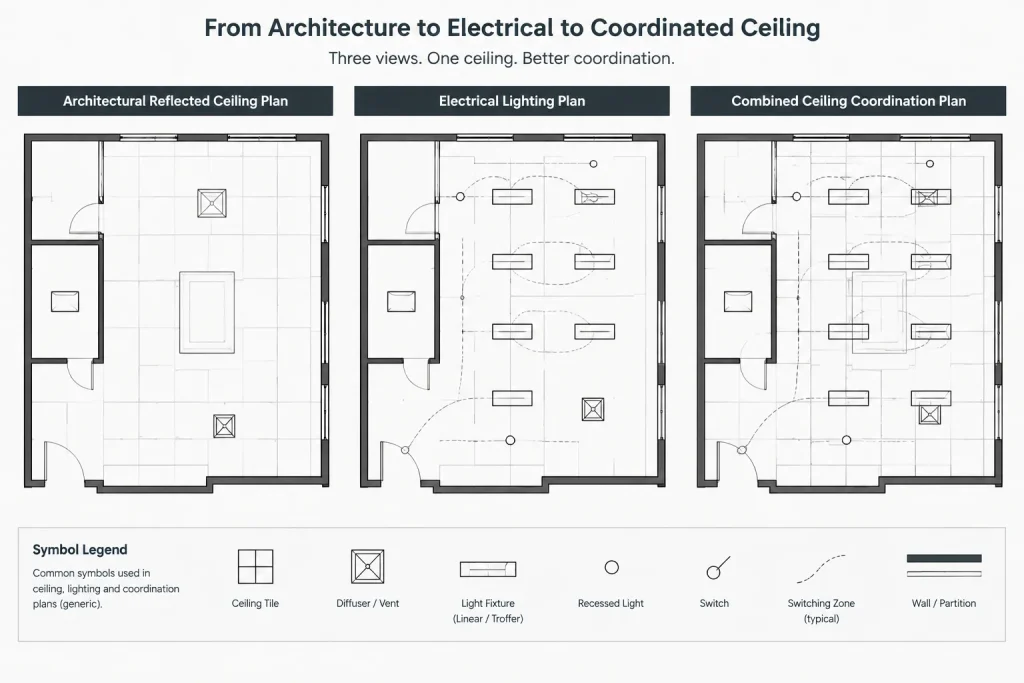
A lighting plan communicates fixture types, circuiting, switching, controls, and related installation intent. A ceiling coordination plan concentrates on physical relationships among ceiling elements. One drawing can sometimes serve both purposes, but only when it remains readable and the project documentation strategy supports that combination.
| Drawing type | Primary purpose | Typical emphasis |
|---|---|---|
| Lighting plan | Document the lighting system | Fixture tags, circuits, controls, switching, and connections |
| Reflected ceiling plan | Document architectural ceiling design | Ceiling materials, grids, heights, soffits, and architectural alignment |
| Ceiling coordination plan | Review multiple ceiling-mounted systems together | Device relationships, congestion, alignment, access, and conflicts |
A coordination plan should not replace discipline-specific plans unless the project team has deliberately established that workflow. Removing circuiting or system information merely because devices also appear on a coordination sheet can create documentation gaps.
Build the CAD View from Controlled References
Use the current architectural ceiling background
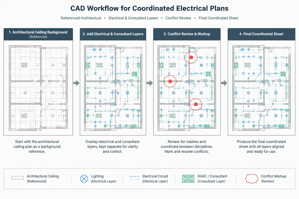
Begin with a controlled external reference or other approved project background. Confirm that its insertion point, units, orientation, and floor designation agree with the electrical files. A reflected ceiling plan may not align with a floor plan if one file has been moved, rotated, or exported from a different coordinate system.
Verify that room names, walls, grids, ceiling boundaries, soffits, and major architectural features are current. If the ceiling design is still developing, identify the background status in the drawing issue notes or coordination record rather than presenting uncertain geometry as final.
Reference other disciplines selectively
Mechanical diffusers, sprinkler heads, access panels, and similar items can help reveal conflicts, but displaying every layer from every consultant often makes the plan unusable. Create a coordination layer state or filtered reference display that retains only relevant geometry.
Reference linework should normally plot with less visual weight than the electrical devices under review. Screening, muted lineweights, or discipline-specific colors can establish hierarchy in working files, while final plotting should remain understandable without relying on color alone.
Organize Symbols and Layers by Function
A single generic ceiling-device layer may be convenient initially, but it limits review and plotting control. Separate major categories so drafters can isolate systems and identify ownership. A project might distinguish lighting, controls, life-safety devices, communications devices, security devices, audiovisual equipment, and reference-only backgrounds.
Use blocks with consistent insertion points. For a ceiling device, the insertion point should usually represent the intended location of the device rather than an arbitrary corner of its graphic extents. This makes alignment, dimensioning, and coordinate comparison more reliable.
Symbols should also remain recognizable when several systems are visible together. Avoid using nearly identical circles or boxes for unrelated devices unless their internal graphics, tags, or legend descriptions provide a clear distinction. Where symbols overlap at the same intended location, do not offset them merely to make the plan look cleaner without documenting what that offset means.
A Practical Ceiling Coordination Workflow
1. Establish the ceiling geometry
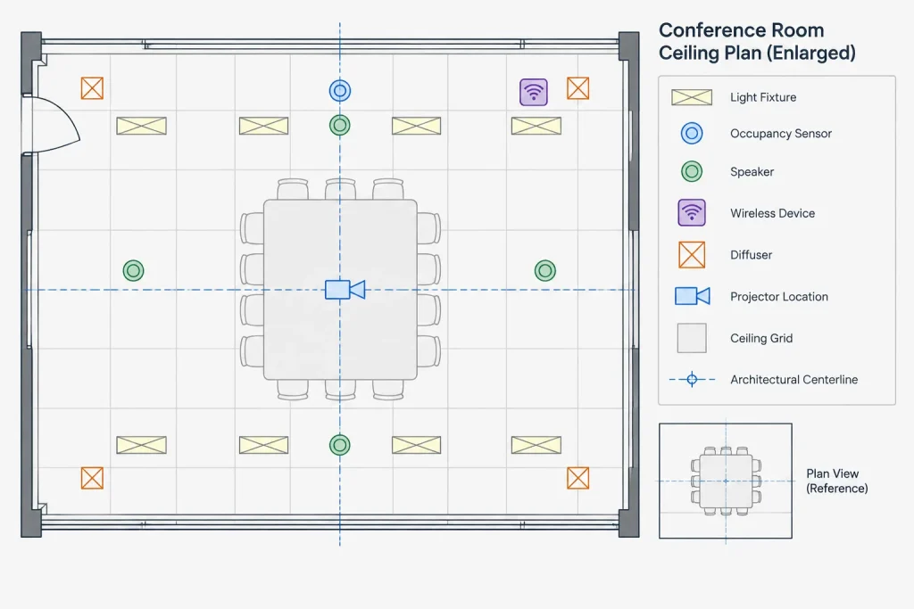
Load the current ceiling background and check the room boundaries, ceiling types, grid orientation, and architectural centerlines. Identify areas with exposed structure, specialty ceilings, sloped surfaces, or ceiling clouds because ordinary grid-based placement assumptions may not apply.
2. Overlay the electrical lighting layout
Review fixture rows, decorative alignments, perimeter conditions, and relationships to furniture or architectural features. A mathematically centered fixture may still conflict with a ceiling tee, access panel, diffuser, or design feature. Where the architecture controls placement, show the relevant reference geometry instead of relying on a note such as “center in room” when the intended center is ambiguous.
3. Add controls and other ceiling devices
Place sensors and other devices using the design information available from the responsible discipline. The CAD symbol should communicate location and identity, but it should not imply unverified coverage, performance, or product capability. If device coverage must be documented, use project-verified design information and distinguish coverage graphics from physical equipment symbols.
4. Overlay coordination references
Display selected devices from mechanical, fire protection, communications, security, and audiovisual drawings. Maintain their source-layer identity where practical. If reference items must be copied into the electrical file, label and manage them as coordination copies so users do not mistake them for authoritative design geometry.
5. Review conflicts systematically
Inspect the plan room by room rather than scanning the entire floor at once. Check device-to-device overlap, alignment with ceiling modules, proximity to access panels, crowded soffits, and objects placed outside valid ceiling boundaries. Also review items near folding partitions, operable walls, tall casework, signage, and ceiling-mounted equipment.
6. Record decisions and unresolved items
Use a coordination markup, issue log, or comment layer to track questions. Each item should identify the location, affected systems, requested decision, and current status. Do not leave temporary clouds, construction lines, or informal notes in an issue file unless they are intentionally part of the published documentation.
Handling Alignment Without Overconstraining the Design
Alignment improves visual order, but not every ceiling device should be forced onto the same centerline. Devices may have different functional, access, or system requirements. The drawing should distinguish intentional alignment from a purely graphical adjustment.
Useful alignment references include:
- Ceiling grid modules and grid intersections
- Room and corridor centerlines
- Fixture rows or architectural reveals
- Door, wall, casework, and equipment centerlines
- Ceiling cloud edges and soffit geometry
If a device must be shifted for drafting clarity rather than physically relocated, use a leader, keyed note, or other established graphic convention. A plan symbol that has been displaced without explanation can be interpreted as the actual installation point.
Common CAD Coordination Problems
- Outdated ceiling backgrounds: Devices appear coordinated to a grid or soffit that has since changed.
- Duplicate symbols: The same device is present in both a consultant reference and the electrical file.
- Unexplained offsets: Symbols are moved away from conflicts graphically, obscuring the intended physical location.
- Layer ambiguity: Users cannot determine which discipline owns or controls an item.
- Excessive background detail: Furniture, hatches, and annotation conceal the ceiling relationships under review.
- Plan-only review: A device appears acceptable in plan but conflicts vertically with a soffit, structure, or suspended element.
- Broken references: External files are unloaded or remapped before plotting, removing critical coordination context.
When to Add Elevations, Sections, or Enlarged Plans
A ceiling plan cannot explain every condition. Use an elevation or section where mounting planes, ceiling steps, suspended elements, or vertical relationships affect interpretation. Enlarged plans are useful for dense areas such as control rooms, lobbies, conference spaces, kitchens, and specialty equipment rooms.
Reference these views directly from the coordination plan. The additional view should answer a specific question, such as which surface receives a device or how equipment relates to a ceiling cloud, rather than simply repeating the plan at a larger scale.
Pre-Issue Review Checklist
- Confirm that the architectural ceiling reference is current and correctly aligned.
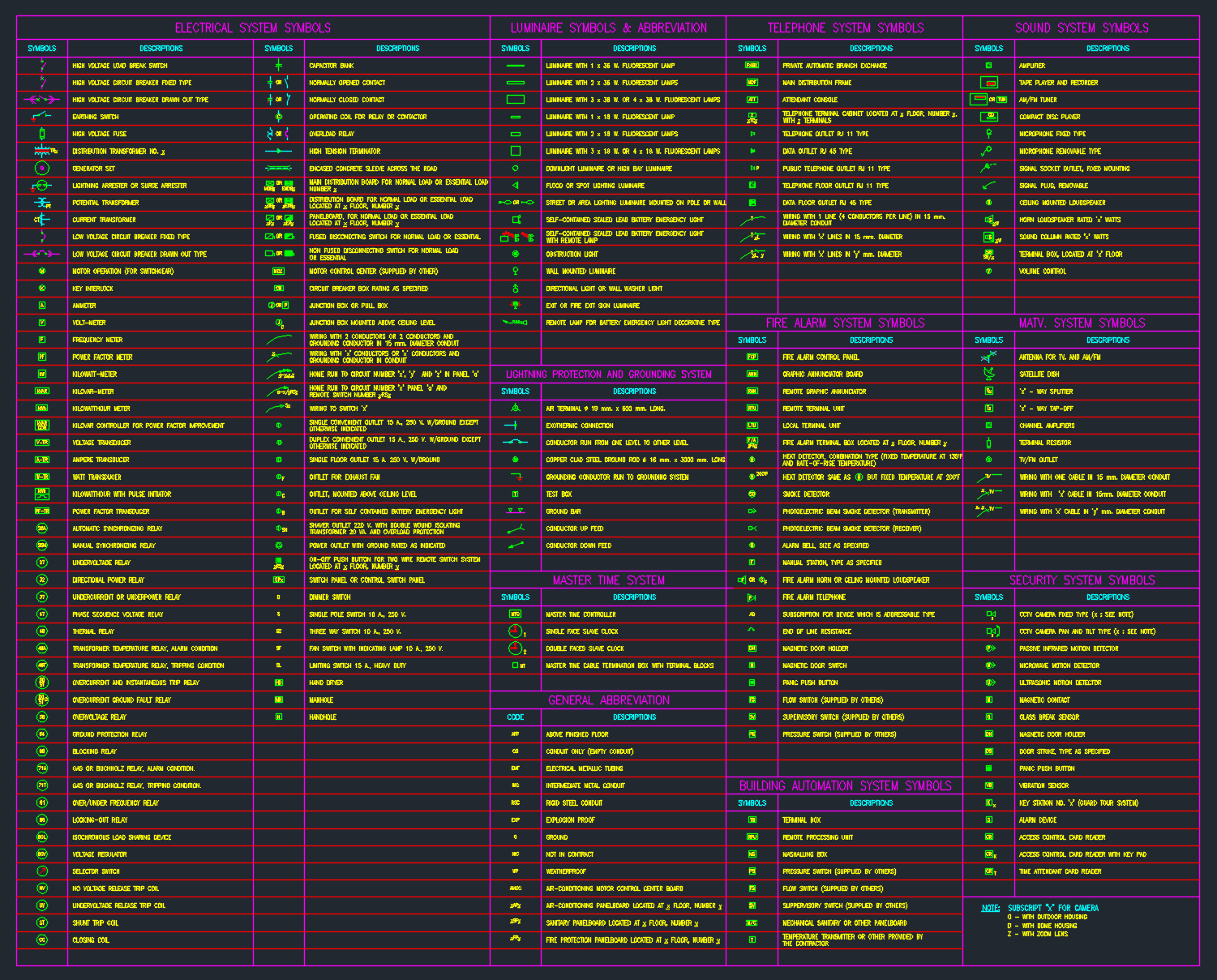
- Check that all visible device types appear in the legend or are otherwise clearly identified.
- Verify that reference-only items are visually distinct from electrical scope.
- Look for duplicate blocks, overlapping symbols, and devices outside ceiling boundaries.
- Compare relevant device locations with lighting, fire alarm, communications, security, and audiovisual plans.
- Confirm that tags remain readable and do not conceal important ceiling geometry.
- Review enlarged areas, sections, and elevations for consistency with the overall plan.
- Plot a test sheet to evaluate lineweight, screening, symbol separation, and monochrome readability.
- Remove or formally resolve temporary coordination notes before issue.
Creating a Reliable Coordination Record
The strongest electrical ceiling coordination plan is not necessarily the one showing the most information. It is the one that clearly identifies device locations, preserves discipline ownership, and makes unresolved relationships easy to find. Controlled references, consistent block insertion points, purposeful layer separation, and room-by-room review turn a crowded ceiling overlay into a useful documentation tool.
Before using any library block or typical detail, verify that its symbol, attributes, scale behavior, and graphic meaning match the project legend and documentation requirements. A CAD block can support coordination, but it does not establish design suitability or project approval by itself.
Apply a Clear Source-of-Truth Hierarchy
A composite ceiling view can reveal conflicts, but it should not quietly become the authoritative design file for every system displayed. When geometry differs between references, identify which discipline controls the item and return the question to that source rather than correcting another discipline’s work inside the electrical drawing.
Classify information by status
- Electrical design information: Devices, tags, connections, and annotations controlled by the electrical documents.
- Coordination reference information: Geometry displayed to evaluate relationships but maintained by another discipline.
- Temporary review information: Markups, clouds, comments, and proposed adjustments awaiting a documented decision.
- Background geometry: Architectural features that establish rooms, ceiling boundaries, grids, soffits, and alignment references.
This distinction can be reinforced through layer names, plotting hierarchy, block attributes, legends, and issue notes. The objective is to let a reviewer understand both what is shown and who is responsible for confirming it.
Review Changes as Relationships, Not Isolated Moves
A relocated ceiling device may affect more than its immediate symbol. After an accepted change, review associated tags, leaders, dimensions, control references, enlarged plans, sections, schedules, and discipline-specific sheets. If the same device appears in more than one view, inconsistent updates can create a conflict even when the coordination plan itself looks correct.
Keep proposed positions separate from accepted locations. A visually clean overlay should not conceal an unresolved decision. Revision tracking, coordination comments, and controlled reference updates provide a more reliable record than moving symbols informally during a review session.
Make the Final Drawing Useful Without Color
Working files may use color to separate systems, but issued drawings should also communicate through lineweight, screening, symbol shape, tags, and legends. Check the plotted output rather than relying only on the CAD display. This review can reveal background geometry that is too prominent, reference devices that resemble electrical scope, or overlapping annotations that obscure the intended installation point.
Frequently Asked Questions
What should be used as the base for an electrical ceiling coordination plan?
Use the current controlled architectural reflected ceiling plan or another approved ceiling background. Confirm its alignment, orientation, floor designation, and revision status before coordinating devices.
Should devices from other disciplines be redrawn in the electrical file?
Controlled references are generally clearer because they preserve source ownership. If geometry must be copied for a project workflow, identify it as reference or coordination information so it is not mistaken for electrical design content.
Can a lighting plan also serve as the ceiling coordination plan?
It can when the project documentation strategy allows it and the combined sheet remains readable. Lighting circuiting, controls, and connections should not be omitted merely because the same drawing is also used to review ceiling relationships.
How should a symbol displaced for graphic clarity be shown?
Use an established leader, keyed note, or comparable drawing convention that identifies the actual device location. An unexplained offset can be interpreted as a physical relocation.
Why are plan views sometimes insufficient for ceiling coordination?
A plan view may not reveal differences in mounting plane, ceiling elevation, suspended construction, soffits, or structural depth. Sections, elevations, and enlarged views can clarify these conditions when vertical relationships affect interpretation.
What should be checked after a coordination change is accepted?
Review every related representation of the affected device, including tags, dimensions, leaders, enlarged plans, sections, schedules, and discipline-specific drawings. Also confirm that temporary review graphics have been removed or formally resolved.




Leave a Reply
You must be logged in to post a comment.