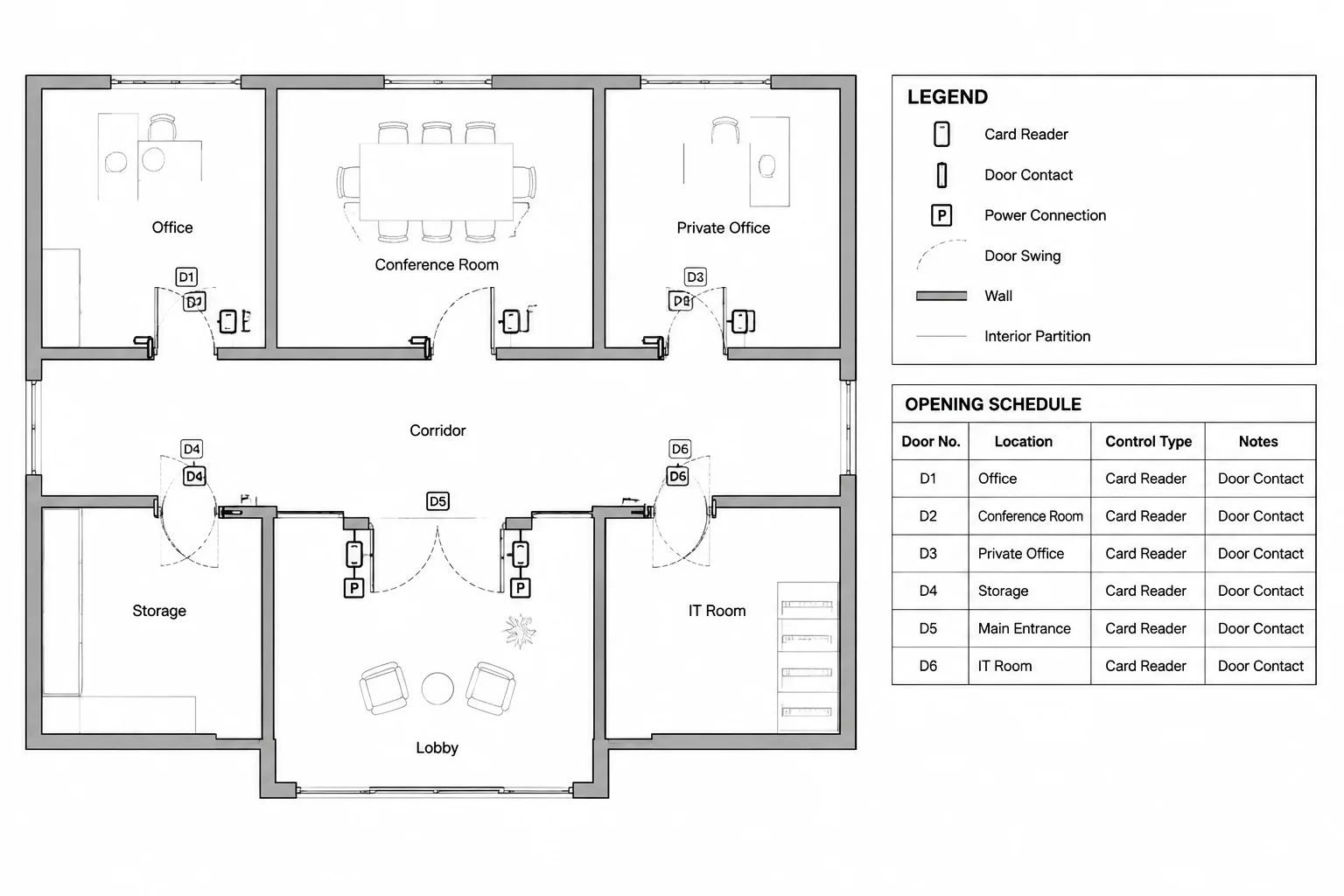
Electrified door hardware drawings in CAD require information from several disciplines to remain aligned as the design develops. The most useful drawing set connects each architectural opening with its visible devices, power source, control relationship, interface requirements, and supporting details without turning the floor plan into a wiring schematic.
This guide explains how to organize those references, manage door-related CAD symbols, distinguish power from control information, and review each opening as a coordinated documentation package. Hardware functions, operating sequences, equipment connections, and construction conditions must still be confirmed against the project documents before issue.
Electrified door hardware often sits at the intersection of architectural, electrical, security, and life-safety documentation. A single opening may involve a lock, exit device, power transfer, position switch, request-to-exit device, access control reader, power supply, fire alarm interface, and connection to a security control panel. If these elements are documented independently, conflicting tags and incomplete connection information can easily reach the issued drawing set.
Electrified door hardware drawings in CAD should therefore do more than place a symbol beside a door. They should establish a traceable path from the architectural opening number to the electrical power source, control function, interface diagram, and applicable detail. The goal is not to reproduce the hardware consultant’s schedule. It is to show the electrical and control information needed for coordination while preserving clear responsibility boundaries.
Begin with the architectural opening reference
The architectural door number is normally the most useful common reference between disciplines. Electrical and security drawings should use that opening identifier consistently rather than creating an unrelated numbering system for each door.
Before adding hardware symbols, review the architectural background for:
- Door numbers and room relationships
- Door handing and swing direction
- Single, paired, sliding, or specialty opening configurations
- Frame and wall conditions
- Hardware set references
- Rated or otherwise specially designated openings
- Doors that appear on enlarged plans or interior elevations
Door information can change during design. Keep the architectural opening number separate from device tags so that a revised reader or lock identifier does not require renumbering the door itself. When backgrounds are updated, compare door numbers, locations, swings, and deleted openings before moving electrical annotations.
Choose what belongs on the floor plan
A floor plan should communicate device location and system association without becoming a miniature wiring diagram. Use plan symbols for items whose physical placement matters, such as readers, door contacts, request-to-exit sensors, local power supplies, control panels, and accessible connection points. Hardware contained within the door or frame may be represented by a coordinated opening tag when individual symbols would make the plan unreadable.
A practical door annotation can include the architectural opening number and a reference to a controlled-opening schedule, security diagram, or hardware detail. Separate visible device locations from functional information. For example, the plan can show which side of the opening contains a reader, while a schedule identifies the lock function and required interfaces.
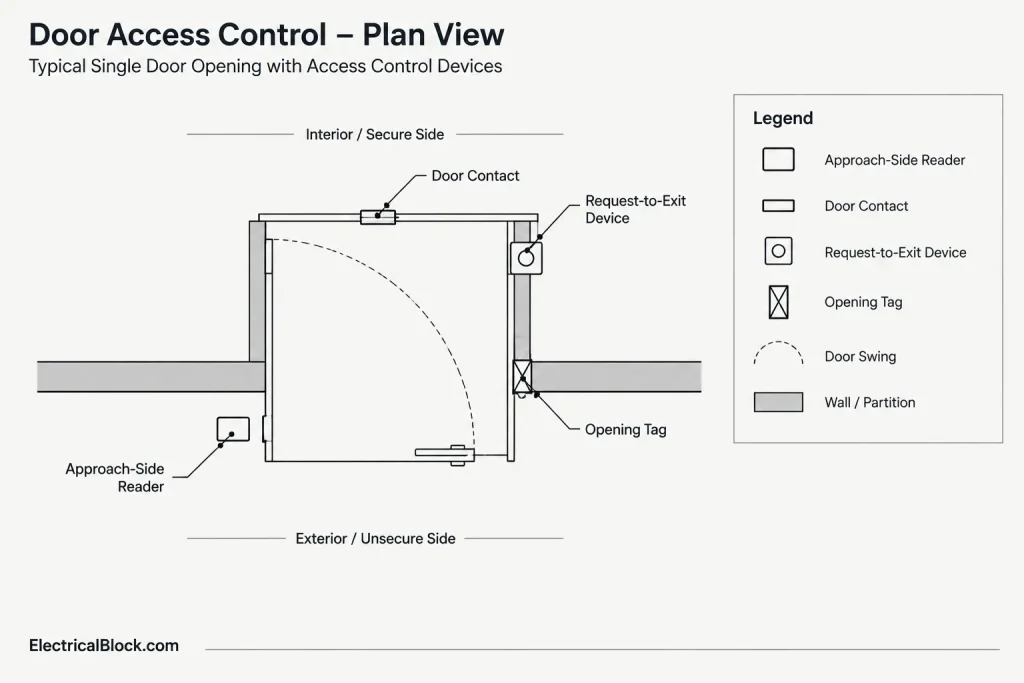
Be careful with symbol position
A symbol placed near a door can be ambiguous unless its relationship to the opening is obvious. A reader symbol should indicate the intended approach side. A door position switch should not appear to be a wall-mounted device. Devices serving paired doors should clearly identify whether they apply to one leaf or the complete opening.
Where several symbols overlap the door swing, use a controlled offset, leader, or grouped door callout. Avoid moving symbols so far away that they appear to serve an adjacent opening. Enlarged plans are often more effective than dense leader networks in vestibules, lobbies, and other door-heavy areas.
Build a coordinated opening schedule
An electrified opening schedule can act as the bridge between the floor plan and the diagrams. It should contain only information supported by the project documents and should not guess at hardware functions or electrical characteristics.
| Schedule field | Coordination purpose |
|---|---|
| Opening number | Connects the entry to the architectural door schedule and plan. |
| Location | Provides a room or area check when door numbers change. |
| Electrified hardware function | Describes the controlled component without relying only on a symbol. |
| Associated devices | Lists readers, contacts, release devices, or other coordinated components. |
| Power source reference | Points to the documented supply, panel, circuit, or system source. |
| Control panel reference | Associates the opening with a security or door control enclosure. |
| Diagram or detail reference | Directs the reader to connection and mounting information. |
| Interface notes | Identifies required coordination with other systems without inventing operation. |
| Responsibility note | Clarifies which discipline or vendor documents each portion of the work. |
Keep fields concise and use controlled terminology. Entries such as “see drawings” are rarely useful unless they include a specific sheet, detail, or diagram reference. Where information has not been confirmed, flag it for resolution rather than filling the schedule with an assumption.
Separate power pathways from control pathways
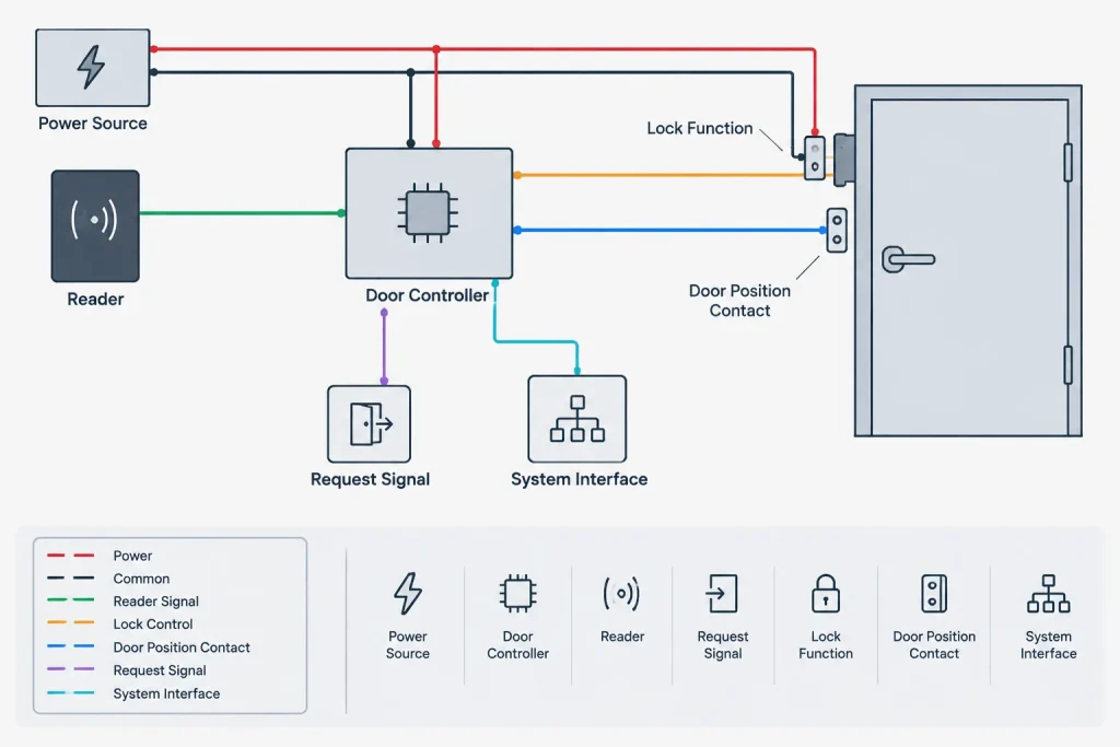
Electrified openings may include both power conductors and signaling or communication pathways. On drawings, these should not be combined into a single unexplained line. Distinct linework, tags, or diagram conventions can show the conceptual relationship without implying an unverified cable type.
The drawing set should make it possible to answer several questions:
- What documented source serves the door hardware?
- Is the source local to the opening or shared by multiple openings?
- Which panel or controller supervises the opening?
- Where does the pathway transition from the wall to the movable door?
- Which connections belong to electrical, security, hardware, or another responsible party?
- Where is the detailed point-to-point information located?
A floor plan can show route intent or connection locations, while a riser or interconnection diagram shows system relationships. Detailed terminal information should be included only when it has been verified against the selected equipment and project requirements.
Document the door-to-frame transition
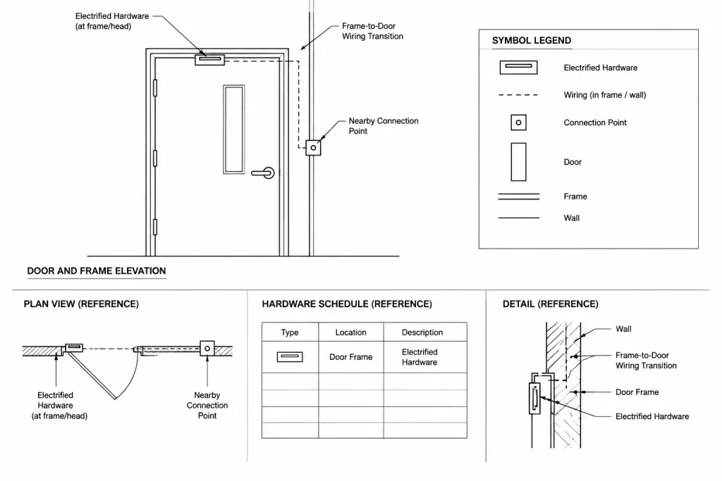
The transition between fixed construction and a moving door leaf is a frequent coordination gap. Depending on the hardware concept, wiring may pass through a listed transfer device, hinge arrangement, or another coordinated assembly. The electrical drawing should identify that a transition is required without substituting a generic CAD block for verified hardware selection.
Use an elevation, jamb detail, or schematic detail to communicate:
- The general transition location
- The relationship between the frame, door leaf, and electrified hardware
- Accessible junction or termination points shown by the design
- References to architectural and hardware documents
- Responsibility for raceway, cabling, hardware preparation, and final connections
Do not infer frame preparation or concealed routing from a generic block. Hollow metal, wood, glazed, storefront, and specialty assemblies may require different coordination. The selected hardware and construction documents must be checked before a detail is treated as project-specific.
Coordinate functional interfaces without inventing sequences
An electrified opening may interact with access control, fire alarm, intrusion detection, intercom, automatic door operation, or building management systems. These relationships are best shown with an interface diagram or sequence reference rather than scattered general notes.
Use plain functional descriptions such as “release interface,” “door status input,” or “request signal” when the exact terminal arrangement has not been selected. Arrows should have a defined meaning: signal direction, sequence relationship, or simple association. Do not use directional arrows decoratively if readers may interpret them as electrical flow or command direction.
Operational states, fail behavior, emergency release functions, and egress implications must be verified by the responsible design team and applicable authorities. CAD documentation should reflect the approved sequence; it should not create one based on a typical detail.
Manage door hardware blocks as a small system
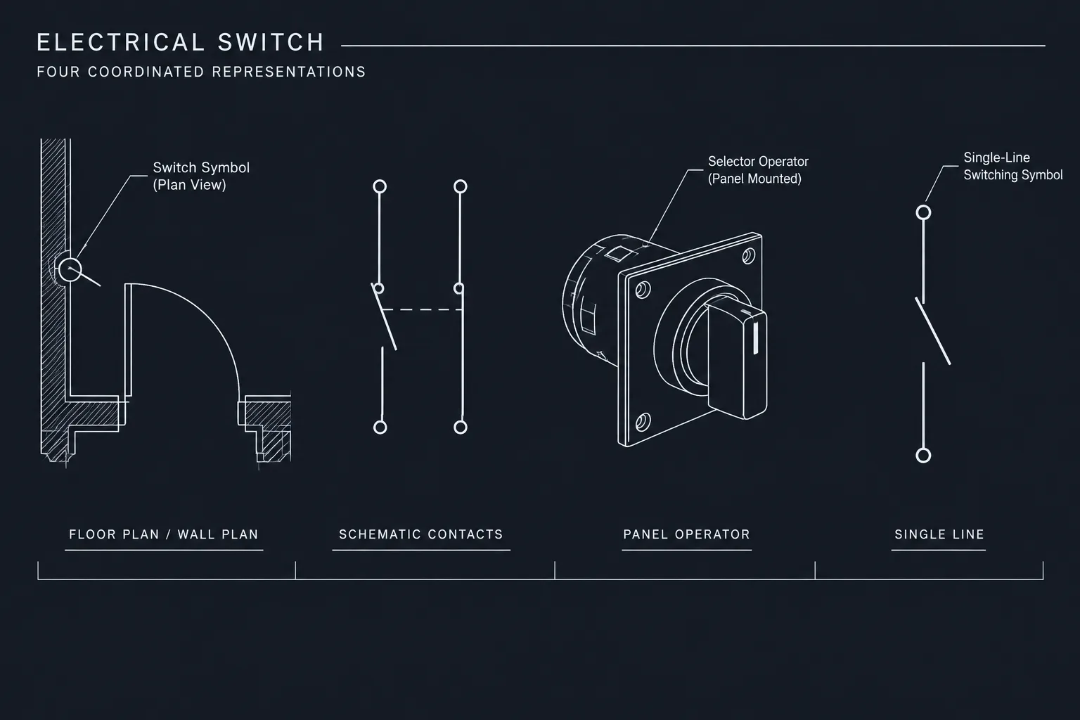
A useful CAD library should distinguish between plan symbols, diagram symbols, and detail components. One oversized universal block is difficult to use consistently across all views.
Consider maintaining related blocks for:
- Plan-view reader and keypad symbols
- Door contact and request-to-exit symbols
- Generic electrified lock or exit device diagram symbols
- Door power supply and controller symbols
- Door transfer indicators
- Opening tags with attributes
- Interface nodes used on risers and control diagrams
Attributes can store the opening number, device tag, system reference, and schedule key. Keep descriptive data independent from visible graphics so tags can be reorganized without redrawing the symbol. If blocks are mirrored for opposite door approaches, verify that text, reader side, and directional indicators remain correct.
Use layers that support review
Layer organization should allow reviewers to isolate the architectural door, electrical power information, security devices, pathways, tags, and coordination notes. Avoid placing every door-related item on one security layer. Functional separation makes overlay review and responsibility checks easier.
A review-friendly layer strategy may distinguish:
- Door device symbols
- Power connection points
- Security or control pathways
- Door tags and schedule references
- Interface annotations
- Existing, new, and removed work where applicable
Layer names and properties should follow the project CAD standard. The objective is controlled visibility, not a universal naming convention.
Perform an opening-by-opening coordination review
Before issue, review each electrified opening as a complete documentation package rather than checking sheets independently. Start at the floor plan, follow the opening into the schedule, locate its power source, trace its control relationship, and confirm the referenced detail.
- Does the door number match the current architectural background?
- Are device symbols shown on the correct side of the opening?
- Does the schedule describe every symbol shown on the plan?
- Is a power source or source reference documented where required?
- Are shared supplies and controllers consistently identified?
- Are power and control pathways distinguishable?
- Is the door-to-frame transition addressed?
- Do diagram references lead to an actual detail or sheet location?
- Are responsibility boundaries clear?
- Have deleted or relocated doors been removed from schedules and diagrams?
This traceable workflow turns door hardware documentation from a collection of nearby symbols into a coordinated drawing system. Generic CAD blocks remain useful starting points, but their tags, functions, interfaces, and installation context must be verified for the actual project before issue.
Make coordination data easy to audit
A drawing can appear complete while still containing disconnected information. A reader symbol may be present on the plan, for example, even though its opening tag is missing from the schedule or its controller reference does not appear on the diagram. Effective documentation lets a reviewer follow the information in either direction: from the door to its source and interfaces, or from a panel and diagram back to every affected opening.
Define the role of each drawing view
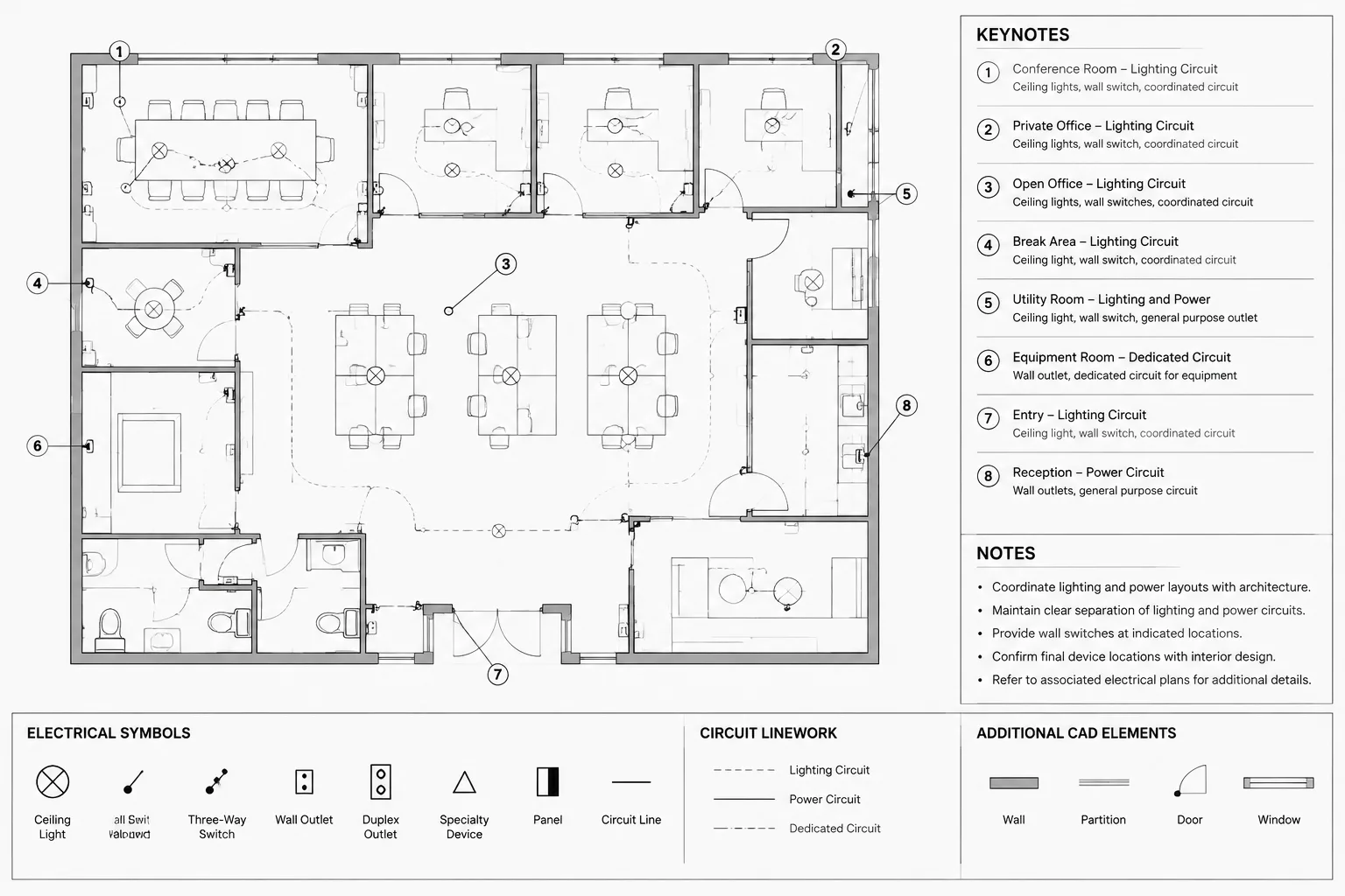
- Floor plans establish physical location, approach side, opening association, and nearby connection points.
- Opening schedules collect supported device, source, interface, and responsibility references.
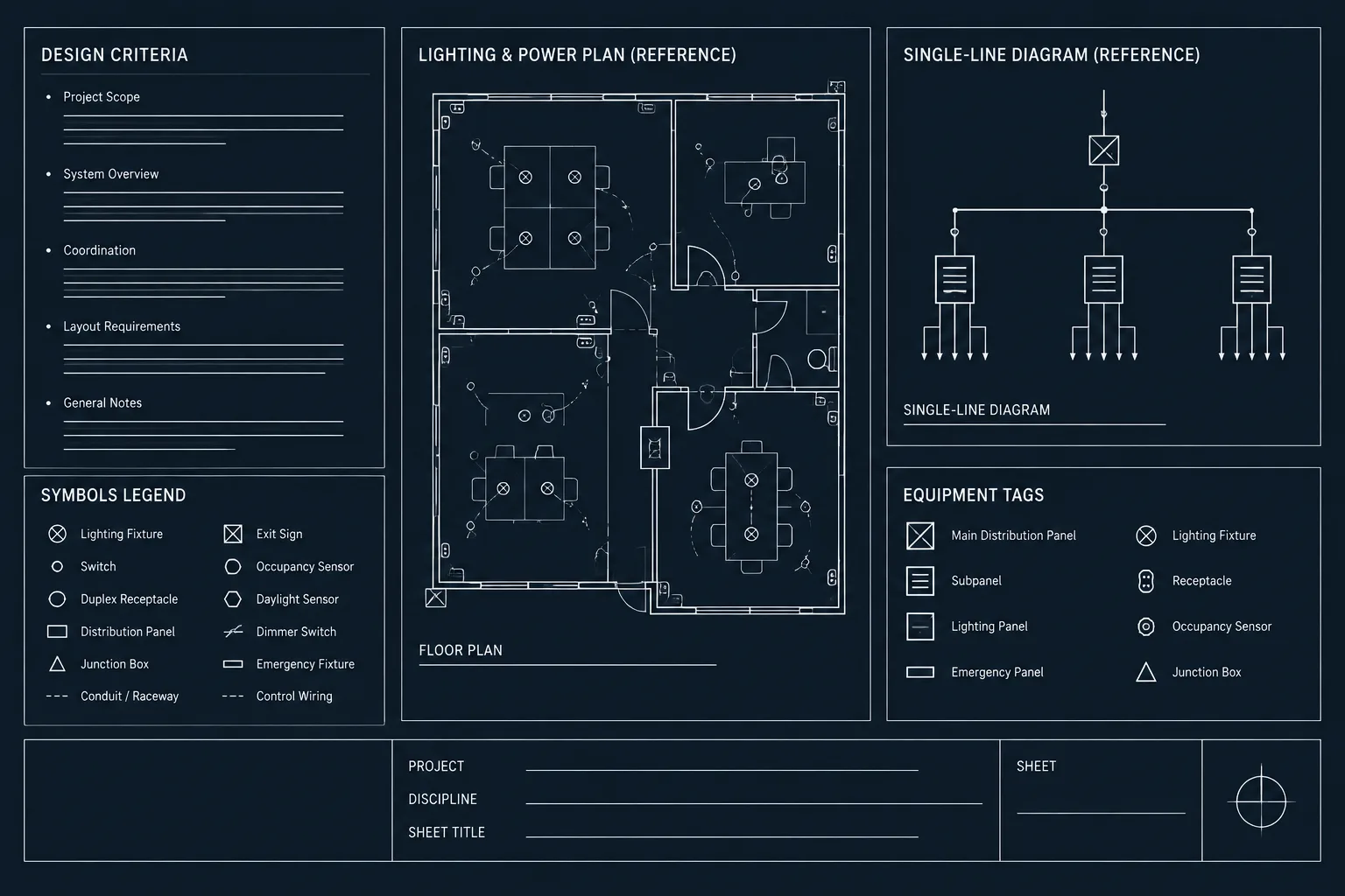
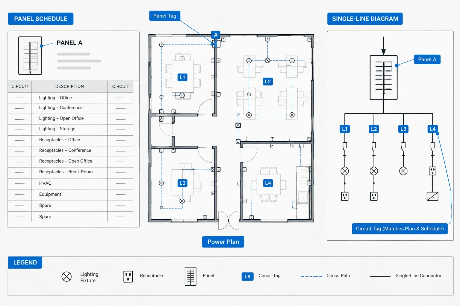
- Risers and interconnection diagrams explain functional relationships between supplies, controllers, interfaces, and openings.
- Details and elevations clarify the relationship among the wall, frame, movable leaf, transfer location, and accessible connection points.
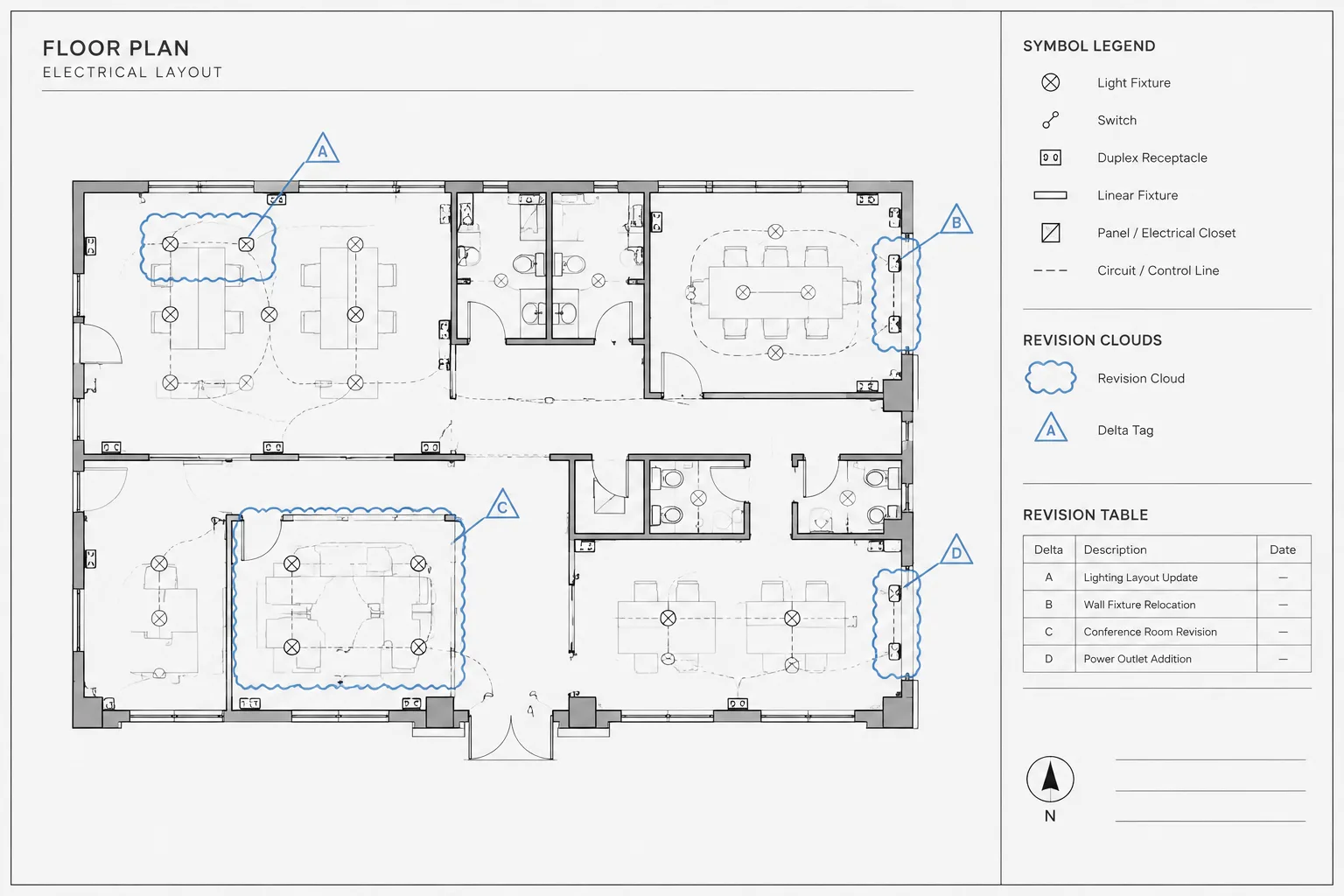
- Legends and notes define symbols, linework, abbreviations, and the intended meaning of arrows or pathway graphics.
Assigning a clear purpose to each view reduces duplicated notes and makes discrepancies easier to find. When the same information must appear in several places, use stable tags and references rather than rewriting long descriptions.
Track unresolved information visibly
Unknown hardware selections, unconfirmed interfaces, and pending responsibility decisions should remain identifiable during coordination. Do not hide them behind a typical block or a vague connection line. A controlled placeholder, coordination note, or review status can show that an item still requires resolution without presenting an assumption as completed design information.
Review revisions by opening, not only by sheet
When an opening moves, changes function, or is removed, the effect may extend to plans, schedules, diagrams, panel references, details, and hardware documents. Revision review should therefore search for the opening identifier and its associated device tags across the complete drawing package. This approach helps prevent abandoned schedule entries, unused controller references, and symbols that remain on outdated backgrounds.
Use generic CAD content with clear limits
Generic door hardware blocks are useful for maintaining graphic consistency, but they do not establish a verified hardware selection or operating sequence. Treat the block as a documentation component whose attributes and references must be completed from approved project information. Avoid embedding assumptions about cabling, frame preparation, fail behavior, terminal assignments, or system responsibility into a symbol that may be reused in different conditions.
A well-managed library supports coordination by keeping plan symbols, diagram nodes, tags, and detail graphics related but separate. That structure allows each representation to match its drawing purpose while retaining a common opening reference.
Frequently asked questions
What should an electrified door hardware plan show?
The plan should show device locations and their association with the correct architectural opening. It may also identify route intent, connection points, source references, and links to schedules or diagrams. Detailed internal connections belong in verified diagrams or equipment documentation rather than crowded plan graphics.
Why should the architectural opening number remain the primary reference?
The opening number provides a common coordination key across architectural, electrical, security, and hardware documents. Device tags can then identify individual components without creating a competing door-numbering system.
Should every hardware component receive a separate plan symbol?
Not necessarily. Symbols are most valuable when physical location or approach side matters. Components concealed within the door or frame may be documented through an opening tag, schedule entry, diagram, or detail when separate plan symbols would reduce clarity.
How should power and control information be distinguished?
Use separate linework, layers, tags, or diagram conventions and define their meaning in the legend. The graphics should communicate different functions without implying an unverified conductor, cable, or terminal arrangement.
Can a generic door transfer block be used as a project detail?
A generic block can indicate that a transition is required, but it should not be treated as confirmation of the selected assembly, frame preparation, concealed routing, or installation condition. Those items require coordination with the applicable hardware and construction documents.
What should be checked when a door block is mirrored?
Confirm the reader side, approach relationship, door swing, directional graphics, leader placement, and text orientation. Mirroring geometry without checking its meaning can associate a device with the wrong side or leaf of the opening.


Leave a Reply
You must be logged in to post a comment.