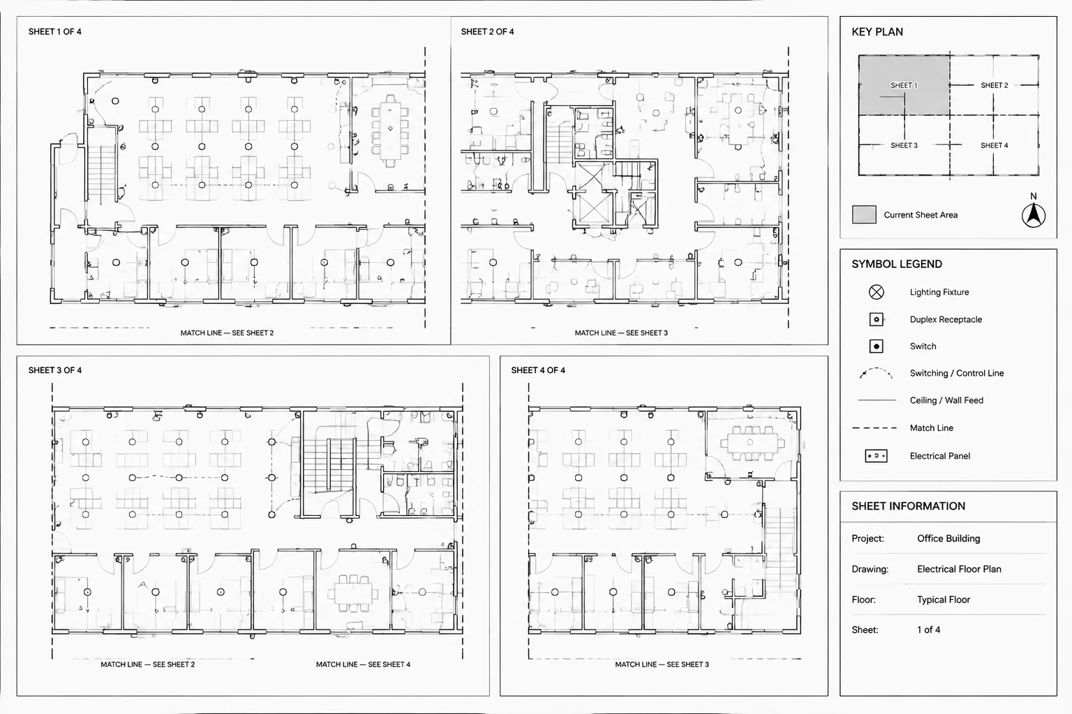
Electrical key plans help readers navigate floor plans divided across multiple sheets. The strongest examples use simplified building geometry, coordinated area boundaries, clear orientation, and sheet-specific emphasis without duplicating the detail shown in the primary plan.
This guide explains how to develop and maintain electrical key plans in CAD as part of a coordinated drawing set. It focuses on drafting decisions, layer control, match-line relationships, plotting behavior, and quality checks that remain useful as plan coverage changes.
Large electrical floor plans are often divided among several sheets so that devices, circuiting, pathways, tags, and notes remain legible. Once a floor is split into multiple drawing areas, the reader needs a quick way to understand where each view is located within the overall building. An electrical key plan provides that orientation.
A useful key plan is more than a miniature floor plan placed in a sheet corner. It communicates the relationship between the current view, adjacent drawing areas, building geometry, and the rest of the electrical set. Drafting it carefully can reduce navigation errors during design reviews, coordination, estimating, and construction documentation.
What Is an Electrical Key Plan?
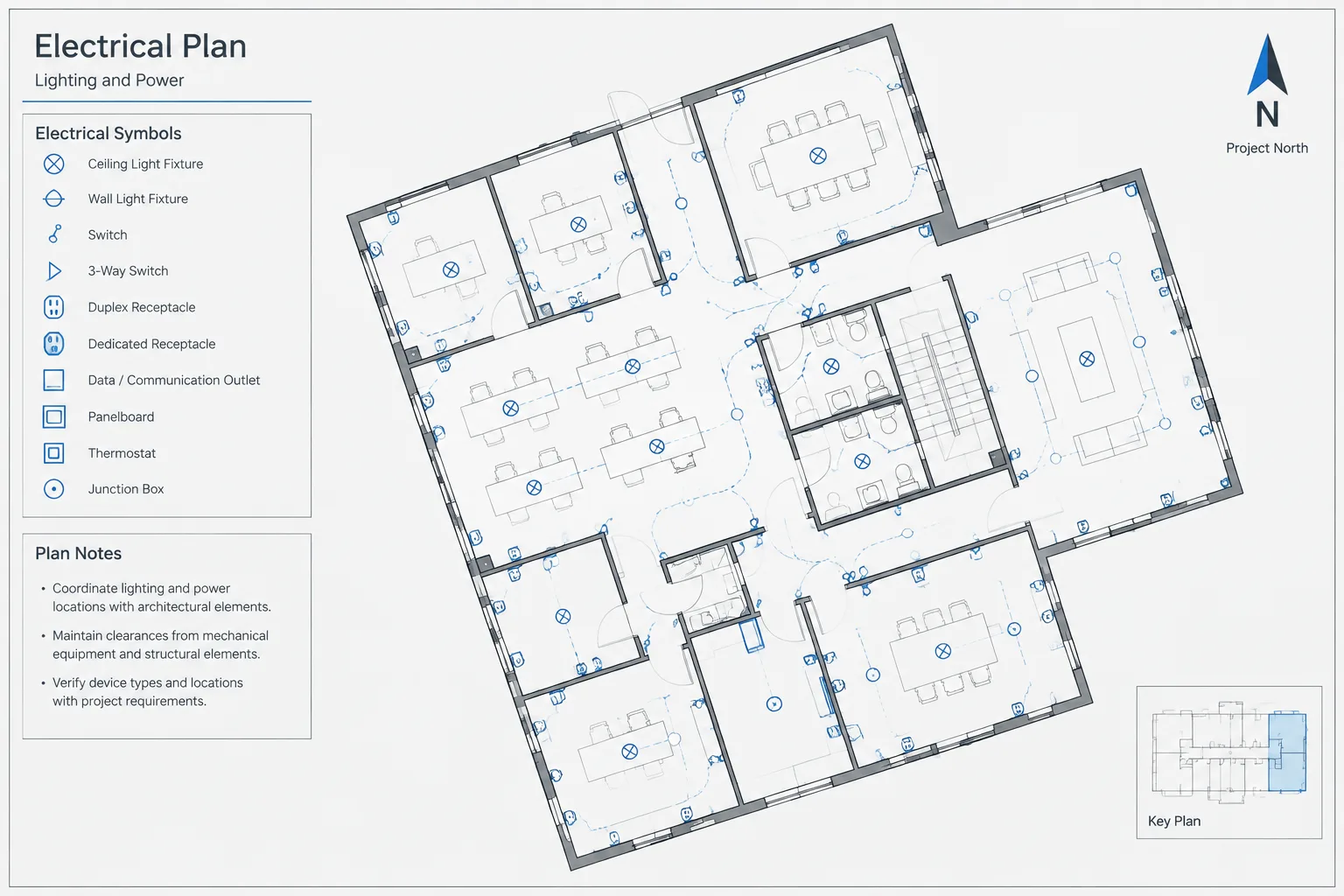
An electrical key plan is a simplified diagram of the building, floor, site, or project area. It highlights the portion represented by the main view on the sheet. On a multi-sheet floor plan, the key plan may show all drawing areas while emphasizing the area covered by the current sheet.
The key plan generally answers several questions:
- Where is this electrical plan located in the building?
- Which wing, level, zone, or area is shown?
- How does the current view relate to adjacent plan sheets?
- Is the displayed plan rotated relative to the project orientation?
- Where should the reader look for continuing work?
Key plans are especially valuable for irregular buildings, repeated floor plates, separate structures, phased work, and plans divided into several enlarged areas.
Key Plan, Match Line, and Vicinity Map: Different Purposes
These drawing tools are related, but they are not interchangeable.
| Drawing element | Primary purpose | Typical information |
|---|---|---|
| Key plan | Shows where the current view fits within the larger project | Building outline, area divisions, highlighted coverage, orientation, and area labels |
| Match line | Defines where plan coverage continues onto another view or sheet | Boundary line, continuation direction, and drawing reference |
| Vicinity map | Locates the project within a broader geographic context | Nearby streets, property context, access routes, or major landmarks |
| Scope diagram | Explains the limits or categories of work | Renovation zones, phases, alternates, or responsibility boundaries |
A key plan can include match-line locations or scope shading, but its central purpose remains sheet orientation. Avoid loading it with information that belongs in the main plan, site plan, or phasing diagram.
Choose the Right Source Geometry
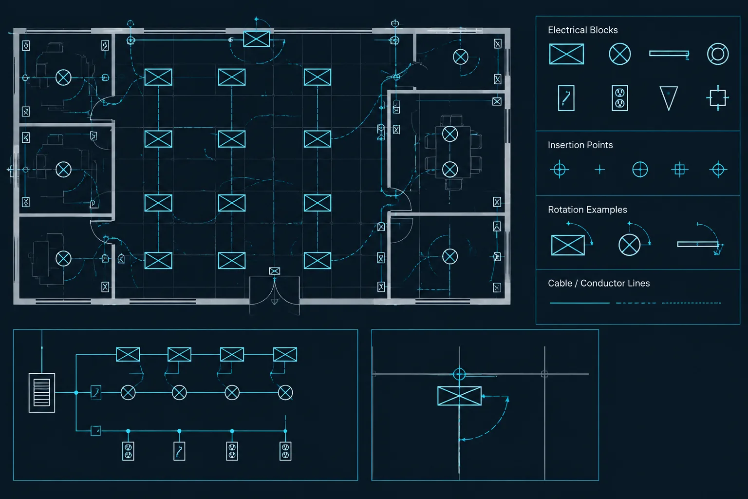
Start with a controlled source rather than redrawing a separate building outline for every sheet. The source may be a simplified CAD block, an external reference, or a dedicated key-plan file used throughout the drawing set.

Include only geometry that helps readers recognize the project layout. Useful elements may include:
- Overall exterior walls or building footprint
- Major wings, cores, courtyards, and expansion joints
- Area boundaries used to divide the electrical plans
- Distinct structures or campus buildings
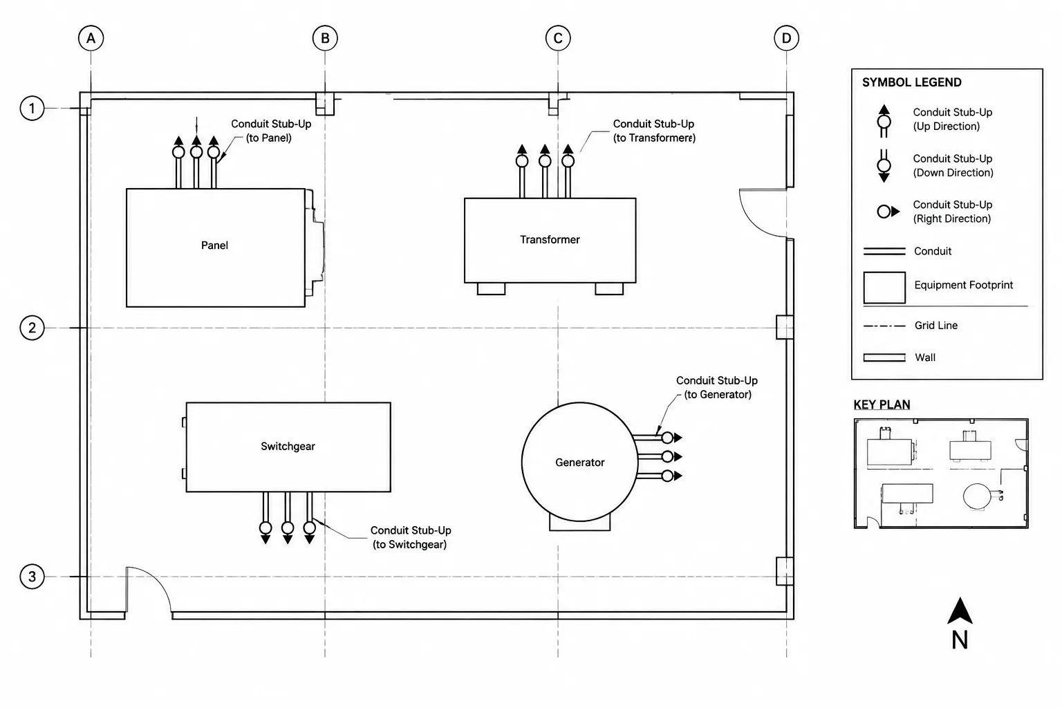
- A project north arrow or other orientation marker
- Brief area, level, or building labels
Remove doors, furniture, room details, equipment, dimensions, dense hatches, and other small geometry that becomes visual noise at key-plan scale. The diagram should remain recognizable after plotting, not merely look detailed when viewed closely in CAD.
Establish Drawing Areas Before Building the Key Plan
Key-plan graphics should reflect actual sheet coverage. Before highlighting areas, define how the electrical floor plan is divided. Consider plan readability, logical building boundaries, architectural area divisions, and the placement of match lines.
Whenever practical, use the same area names across disciplines. If architectural sheets use named wings or area designations, the electrical key plan should not introduce a conflicting system without a clear project reason. Shared terminology makes overlay reviews and consultant coordination easier.
Confirm that every portion of the floor is covered and that overlaps or gaps are intentional. A key plan can expose a documentation problem early: an unassigned sliver of floor area, an inconsistent boundary, or two sheets claiming different extents.
Highlight the Current Sheet Clearly
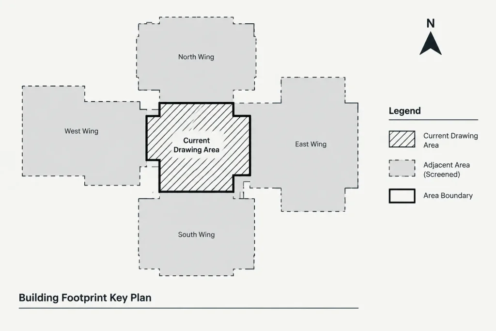
The current drawing area must be visually dominant without obscuring the overall building form. Common methods include a solid fill, screened hatch, bold outline, or contrasting plot treatment. Select a method that remains understandable in both color and monochrome output.
Do not depend on color alone. Review copies may be printed without color, converted to grayscale, or viewed on displays with varying settings. Combining fill or screening with a distinct boundary generally creates a more reliable result.
Adjacent areas can remain unfilled or receive a lighter treatment. If other areas are labeled, keep their labels subordinate to the highlighted area. The reader should identify the current location at a glance.
Coordinate Orientation with the Main View
A key plan may follow project north while the main plan is rotated to fit the sheet. That difference must not be ambiguous. Include an orientation indicator where needed and use the same directional convention throughout the set.
There are two workable approaches:
- Fixed project orientation: Every key plan retains the same orientation, regardless of how the main viewport is rotated.
- View-matched orientation: The key plan rotates to align with the main plan shown on that sheet.
Either approach can work if it is applied consistently and clearly. A fixed orientation helps readers compare sheets, while a view-matched orientation can make immediate navigation easier. Mixing both approaches without an obvious cue creates confusion.
Connect Key Plans to Match Lines and Sheet References
The key plan shows the overall relationship; match lines manage the exact continuation between views. Their area boundaries should agree. If the main plan ends at a match line, the highlighted region in the key plan should not imply substantially different coverage.
Where appropriate, label adjacent drawing areas or identify the sheets containing them. Keep references concise and verify them against the sheet index before every issue. Sheet identifiers often change as a set develops, making manually entered references vulnerable to becoming outdated.
Avoid duplicating every continuation note inside the key plan. Detailed references belong at the relevant match lines in the main view. The key plan should support navigation rather than become a second sheet index.
A Maintainable CAD Workflow
1. Create a simplified master diagram
Develop one authoritative floor or building outline. Place recognizable geometry and area boundaries on controlled layers. Keep the master diagram separate from sheet-specific highlighting where possible.
2. Define area graphics consistently
Create closed boundaries for each drawing area. Use a repeatable hatch, fill, or outline system for current and adjacent coverage. Check that boundaries do not leave unintended gaps.
3. Add sheet-specific emphasis
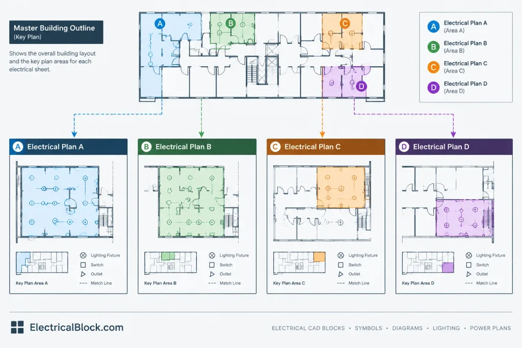
For each sheet, highlight only the area represented by its primary plan view. If a sheet contains several plan views, clarify whether the key plan identifies all of them or whether separate indicators are needed.
4. Place the key plan predictably
Use a consistent location and approximate plotted size across related sheets. Repeated placement helps readers find it quickly and gives the drawing set a coordinated appearance.
5. Control layers and plotting
Separate the building outline, area divisions, labels, fills, and orientation symbols when practical. This allows graphic adjustments without editing the underlying geometry. Test screening, lineweight, and hatch behavior in the actual plotted output.
6. Update from the source
When the architectural footprint or plan division changes, revise the controlled source and propagate the update. Avoid independent copies that drift apart over successive issues.
Common Key-Plan Problems
- Too much architectural detail: Dense geometry makes the diagram unreadable at its plotted size.
- Incorrect highlighted area: Copied sheets may retain the highlight from a previous view.
- Uncoordinated boundaries: Key-plan divisions do not match the main plan match lines.
- Weak monochrome output: Areas distinguished only by color become indistinguishable when printed.
- Missing orientation: A rotated main view cannot be confidently related to the overall building.
- Stale sheet references: Adjacent-sheet labels are not updated after the drawing list changes.
- Inconsistent area names: Electrical, architectural, and mechanical drawings use different labels for the same location.
- Oversized graphics: The key plan competes with notes, legends, or the primary electrical plan.
Quality-Control Checklist
Before issuing a multi-sheet electrical plan set, review each key plan alongside its main viewport:
- Does the highlight accurately represent the view shown on the sheet?
- Are all building wings and project areas represented correctly?
- Do area boundaries align with the applicable match lines?
- Is orientation clear when the main plan is rotated?
- Are area names consistent with the rest of the project?
- Do adjacent-sheet references match the current sheet list?
- Can the current area be identified in monochrome output?
- Is the graphic legible at the intended plotted size?
- Has unnecessary background detail been removed?
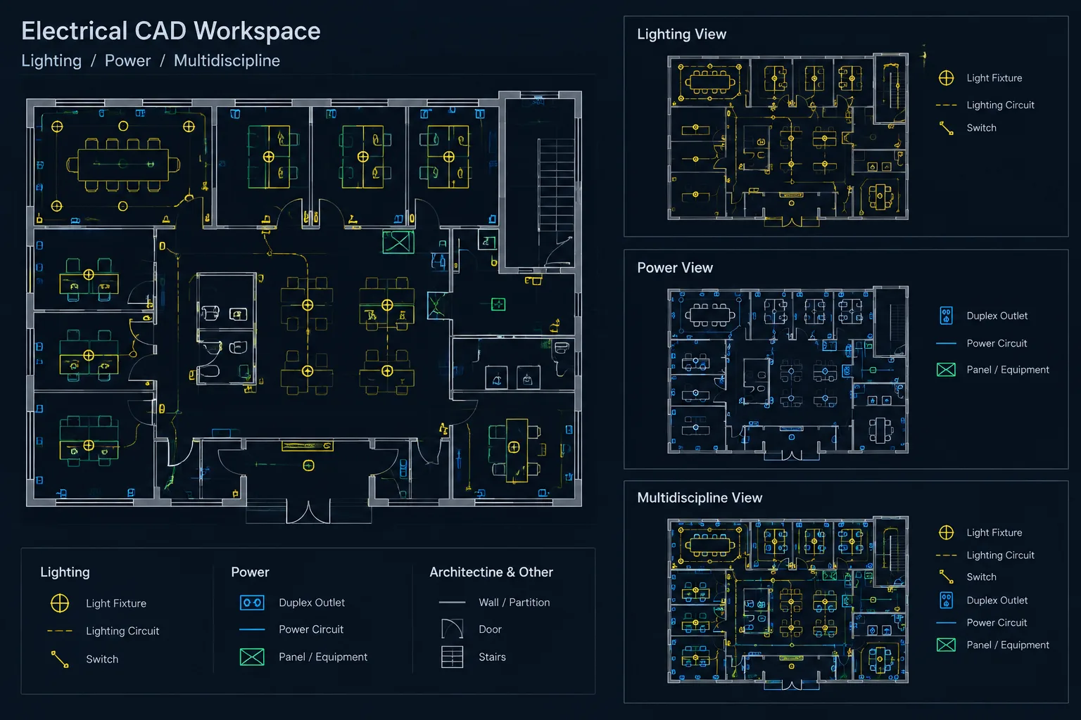
- Are key plans consistent across lighting, power, and other electrical plan series?
Key Plans as Part of the Navigation System
An effective electrical key plan works with title blocks, sheet titles, match lines, callouts, and the drawing index. It should not repeat all of those elements, but it should reinforce the same organizational logic.
Treat the key plan as controlled project information rather than decorative sheet graphics. A simplified master source, consistent area boundaries, reliable highlighting, and routine plotting checks produce a navigation aid that remains useful as the electrical drawing set evolves.
Managing Key Plans Through Drawing Revisions
Key-plan quality depends on change management as much as graphic design. A floor-plan division that works during an early issue may change after view scales, sheet organization, or architectural geometry are revised. Treat area boundaries, labels, and references as coordinated drawing data that must be reviewed whenever the main plans change.
Assign responsibility for the master key-plan geometry within the CAD workflow. Team members should know which file or referenced source controls the building outline and which sheet elements provide local highlighting. This reduces the risk of users editing detached copies that no longer agree with the current floor plans.
Separate location from work scope
The highlighted key-plan area normally identifies the geographic extent of the view. It does not automatically mean that every electrical element within that area is part of the same construction phase, discipline responsibility, or renovation scope. If scope information is required, use a clearly differentiated graphic convention and explain it in the drawing legend or notes.
Review the key plan in sheet context
A key plan should be checked in the completed sheet layout rather than only in model space. Confirm that its linework, fill, labels, and orientation remain readable beside the title block, notes, legends, and primary viewport. Also verify that viewport clipping or layer overrides have not removed essential geometry.
Include key plans in coordination reviews
When sheets are added, removed, renamed, or reorganized, review the complete key-plan series together. Comparing the sheets side by side can reveal duplicate highlights, missing coverage, inconsistent labels, and boundaries that shift between lighting and power plans. This set-level review is often more effective than checking each sheet independently.
Frequently Asked Questions
Should every electrical floor-plan sheet have a key plan?
A key plan is most useful when the reader needs help locating a partial view within a larger floor, building, or site. A sheet showing the complete project area may not need one if its location and orientation are already clear. Apply the project documentation convention consistently.
Should a key plan show electrical devices and circuiting?
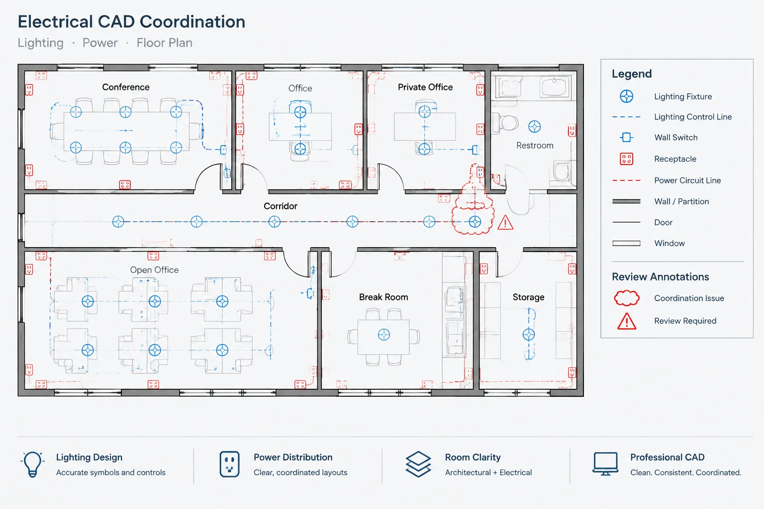
Usually not. Device symbols, circuiting, detailed pathways, and room-level information can make the reduced diagram difficult to read. Retain only the geometry and annotations needed to recognize the building and understand the displayed coverage.
Can the same key plan be used for lighting and power sheets?
The same controlled base geometry can support both plan series when their drawing areas agree. Each sheet still needs the correct local highlight, orientation, and references. If the series use different coverage boundaries, their key-plan graphics must reflect those differences.
What is the best way to show the current area?
Use a graphic treatment that remains distinct in the intended plot output. A fill, hatch, screening, or heavier boundary can work, but the result should not rely on color alone or obscure the overall building outline.
Should adjacent sheet numbers appear in the key plan?
They may be useful when kept concise and carefully maintained. Exact continuation references generally belong at match lines in the main plan, while the key plan provides broader orientation. Avoid turning the diagram into a duplicate sheet index.
How should repeated floors be handled?
Identify the applicable level or floor clearly and confirm that the displayed geometry represents that level. Similar floor plates can cause navigation errors when labels, cores, wings, or plan extents differ subtly between sheets.
Leave a Reply
You must be logged in to post a comment.