
Photometric plans in CAD connect lighting calculation output with the geometry and fixture information used in construction documents. Successful coordination depends on more than a clean import: the calculated points, luminaire references, boundaries, backgrounds, and revisions must remain traceable across the drawing set.
This drafting guide outlines a practical workflow for organizing photometric data, checking alignment, managing graphic density, and documenting calculation sources. It is intended as a drawing-coordination reference and does not establish lighting criteria or replace project-specific review by the responsible professionals.
A photometric plan communicates predicted lighting performance across a site, room, roadway, parking area, or other defined space. Unlike a conventional lighting plan, which primarily shows fixture locations and control relationships, a photometric drawing may include calculation points, result grids, contour lines, calculation boundaries, and summary data.
These drawings are often produced by specialized lighting calculation software and then coordinated with CAD backgrounds. The drafting challenge is not simply importing the results. Fixture locations, calculation assumptions, architectural geometry, and drawing revisions must remain aligned while the finished sheet stays readable.
This guide explains how to integrate photometric information into an electrical CAD workflow. It focuses on drawing organization and documentation rather than selecting fixtures or establishing project acceptance criteria.
Photometric Plan Versus Lighting Plan
A lighting plan and a photometric plan are related, but they answer different questions.
| Drawing type | Primary purpose | Typical content |
|---|---|---|
| Lighting plan | Documents the physical and electrical lighting layout | Fixture symbols, type tags, circuiting, controls, mounting references, notes, and schedule coordination |
| Photometric plan | Documents calculated lighting performance | Calculation points, predicted values, contours, zones, summaries, assumptions, and fixture references |
| Combined plan | Shows layout and selected calculation information together | Fixture locations, simplified results, calculation boundaries, and references to supporting reports |
Combining everything on one sheet can be useful for a small or visually simple project. A separate photometric sheet is usually clearer when dense point grids or multiple calculation zones would obscure construction information.
Begin with a Controlled Background
The calculation model and the construction drawing should use the same current project geometry. Before coordinating results, confirm the source, date, orientation, units, and base point of the architectural or civil background.
For exterior studies, review the geometry that affects fixture placement and calculation areas, such as building outlines, parking rows, drives, walkways, property limits, canopies, walls, and landscape zones. For interior studies, coordinate room boundaries, ceiling conditions, work areas, partitions, and significant obstructions represented in the model.
Keep the background as a referenced file when practical rather than copying all geometry into the photometric drawing. This helps separate consultant information from electrical content and makes later background updates easier to identify.

Check alignment before reviewing values
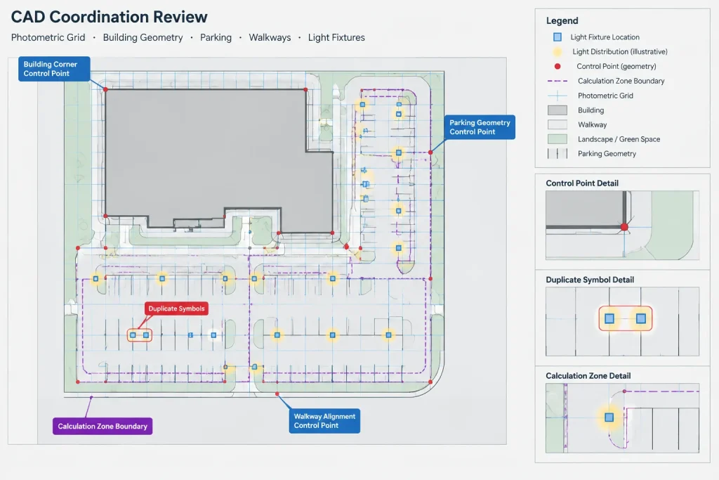
A calculation grid can look plausible even when it is shifted, rotated, or scaled incorrectly. Use recognizable control points to check alignment, including building corners, grid intersections, curb returns, column lines, or other stable project features. Do not rely only on visually matching one fixture symbol.
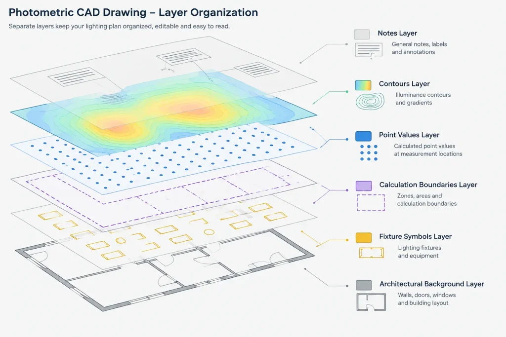
Organize Photometric Content by Function
Imported calculation output often arrives as a large collection of lines, text, blocks, or fills. Separating that information by function makes it easier to display, review, and update.
A practical layer structure may distinguish:
- Calculation point markers
- Calculated value text
- Contour or isoline graphics
- Calculation zone boundaries
- Fixture symbols generated by the calculation model
- Calculation notes and summaries
- Imported reference geometry
- Nonprinting review or alignment aids
Use project layer standards where they exist. The objective is not to create a special layer for every object, but to let drafters control major information groups independently. For example, contour lines may be useful on a presentation sheet but unnecessary on a construction lighting plan.
Coordinate Fixture Identities Across Documents
The same luminaire may appear in the lighting plan, fixture schedule, photometric model, site plan, and equipment submittal. A consistent type identifier helps reviewers trace the fixture across those sources.
Before issuing a photometric sheet, compare the following:
- Fixture type tags
- Fixture quantities and locations
- Mounting condition descriptions
- Orientation or aiming indicators where applicable
- Pole, arm, wall, ceiling, or canopy relationships
- References to the current lighting fixture schedule
A calculation symbol should not silently replace the project lighting block if the two symbols communicate different information. One approach is to keep the electrical fixture block as the primary construction symbol and place calculation graphics on separate layers. Another is to use a dedicated photometric symbol that clearly carries the same fixture type tag.
Watch for duplicate fixture graphics
When calculation output is placed over an electrical lighting plan, duplicate symbols may overlap. This can create heavy linework or make a fixture appear to have moved. Decide which symbol set governs the sheet and suppress or screen the secondary set without deleting information needed for coordination.
Show Calculation Areas Clearly
A value has meaning only when the reader understands what area it represents. Use boundaries, labels, hatching, or restrained screening to identify calculation zones. Examples might include a parking field, pedestrian path, interior work area, loading zone, entrance, or canopy.
Calculation zone names should remain stable across the drawing, result summary, and supporting report. Avoid generic labels that are difficult to trace after the project gains additional areas.
If a zone is intentionally excluded, indicate that condition clearly rather than leaving an unexplained gap in the point grid. The drawing should help a reviewer distinguish between an omitted calculation, an obstructed area, and a deliberate boundary.
Manage Point Grids and Contours for Readability
Photometric point grids can quickly dominate a drawing. Treat calculated values as an annotation system rather than as ordinary background text.
- Use a consistent text style and plotted size appropriate to the sheet.
- Prevent result text from colliding with fixture tags, dimensions, room names, or civil labels.
- Screen secondary background information while keeping boundaries recognizable.
- Avoid placing opaque masks over information needed to interpret the calculation area.
- Use contours selectively when they improve understanding rather than merely adding density.
- Create enlarged views when a critical area cannot be read at the primary plan scale.
Moving calculated values manually should be avoided unless the documentation clearly preserves their relationship to the original points. A displaced value can be mistaken for a result at a different location. If annotation must be offset, use a method that keeps the source point unambiguous.
Document Assumptions Without Overloading the Plan
The CAD sheet should identify enough context for the calculation to be interpreted, but it does not need to reproduce every field from the calculation software. Detailed input and output data can remain in a referenced calculation report.
Depending on the project, useful drawing information may include:
- Calculation file or report identifier
- Date or revision of the calculation output
- Fixture type references
- Calculation zone names
- Relevant modeled mounting or orientation conditions
- A statement identifying whether values are calculated rather than field measurements
- References to related plans, schedules, details, or reports
Only include assumptions that have been verified by the project team. Do not infer mounting conditions, surface properties, fixture performance, or acceptance criteria from a generic CAD block.
Use a Deliberate Update Workflow
Photometric information can become outdated when fixture locations, building geometry, paving, room layouts, or selected luminaires change. Treat the calculation output as a coordinated project source rather than static decoration.
- Record the source. Identify the model or report from which the CAD graphics were generated.
- Preserve the previous issue. Archive or revision-control earlier output according to the project workflow.
- Compare backgrounds. Check whether relevant architectural, civil, or electrical geometry changed.
- Replace results as a group. Avoid mixing point values from different calculation runs.
- Recheck fixture tags. Confirm that the calculation model still matches the lighting plan and schedule.
- Review sheet graphics. Imported text and contours may require new visibility or clipping adjustments.
- Plot-test the sheet. Verify legibility in the actual issue format, not only at full zoom in CAD.
A visible note such as a calculation revision identifier is often more reliable than trying to determine currency from object creation dates within the drawing file.
Common Coordination Problems
Results are aligned to an obsolete background
The point grid may match an earlier parking layout or room configuration. Compare stable control points and review changed boundaries before accepting the overlay.
Fixture tags differ between the model and schedule
This breaks the traceability of the calculation. Create a reconciliation list rather than changing tags in only one document.
Imported output cannot be controlled
Results placed on a single layer are difficult to simplify. Separate values, contours, boundaries, symbols, and notes during cleanup when the source format permits it.
The sheet does not distinguish calculated data from construction annotation
Use clear titles, notes, layer hierarchy, and graphic treatment so point values are not confused with elevations, circuit numbers, dimensions, or equipment tags.
Only the average result is visible
A summary alone may hide where a value applies. Pair summary information with clearly labeled calculation zones and retain detailed results in the plan or supporting report as appropriate.
Photometric CAD Review Checklist
- Confirm the background source, orientation, units, and base point.
- Verify that calculation zones match the current project geometry.
- Compare fixture locations and type tags with the lighting plan.
- Check for duplicate or conflicting fixture symbols.
- Confirm that result text remains associated with the correct points.
- Separate calculation graphics into controllable information groups.
- Identify the calculation output date or revision.
- Reference supporting reports where detailed assumptions are stored.
- Review enlarged or congested areas at plotted scale.
- Confirm that the sheet clearly distinguishes predictions from measured conditions.
A Coordinated Drawing, Not Just an Imported Grid
A useful photometric plan is more than calculation output placed over a CAD background. It connects predicted results to current geometry, identifiable fixture types, named calculation areas, and traceable project documents.
By controlling layers, preserving coordinate alignment, coordinating fixture identities, and recording the calculation source, drafters can produce photometric sheets that are easier to review and maintain. Final lighting criteria, calculation methods, and product data should always be verified by the responsible project professionals rather than assumed from symbols or example drawings.
Define the Role of Each Project File
A coordinated workflow should identify which file governs each type of information. The architectural or civil background typically establishes physical geometry, the electrical lighting plan documents the construction layout, and the calculation model produces predicted lighting results. The photometric sheet brings those sources together without making them interchangeable.
Define whether the CAD photometric content is a live reference, a controlled export, or an issued snapshot. This distinction matters during revisions. Editing imported point values directly may make the sheet appear current while separating it from the calculation model that generated the results.
Preserve traceability through the handoff
When calculation output moves between a lighting application and CAD, retain enough source information for another team member to identify the corresponding model or report. File names, issue descriptions, zone labels, fixture tags, and revision records should follow the project documentation method. Avoid relying on informal folder locations or individual memory.
Review the Sheet as a Communication Layer
The final review should consider what a reader can determine from the plotted drawing. A reviewer should be able to distinguish calculated results from dimensions and construction annotations, identify the area represented by each group of values, and trace modeled fixtures back to the lighting documentation.
- Geometry check: Confirm that calculation boundaries follow the intended rooms, paved areas, walkways, or other modeled spaces.
- Identity check: Compare fixture tags and locations with the coordinated lighting plan and schedule.
- Source check: Confirm that the displayed results came from the intended calculation issue.
- Graphic check: Review text hierarchy, linework, screening, clipping, and overlaps in the plotted format.
- Change check: Determine whether revised backgrounds, fixture selections, mounting conditions, or orientations require the model to be recalculated.
This approach keeps the photometric plan connected to the broader drawing set while avoiding unsupported conclusions from isolated CAD graphics. Project criteria, calculation assumptions, product performance, and final compliance decisions remain subject to verification by the responsible design team.
Frequently Asked Questions
Is a photometric plan the same as an electrical lighting plan?
No. A lighting plan primarily communicates fixture layout, controls, circuiting, tags, and construction references. A photometric plan communicates predicted lighting performance through calculation points, contours, zones, summaries, or related output. A project may combine selected information, but the functions remain distinct.
Should photometric results be imported into model space or placed directly on a sheet?
The appropriate method depends on the project CAD workflow. Results associated with project geometry are generally easier to coordinate when they retain consistent drawing coordinates. Sheet presentation can then be managed through viewports, clipping, layer visibility, and annotation controls.
Can imported photometric values be moved to improve readability?
Moving a displayed value can make its source location unclear. If an annotation must be offset, the drawing should preserve an unmistakable connection to the original calculation point. Reformatting or regenerating the output is preferable when manual movement could change how the result is interpreted.
What should happen when the architectural or civil background changes?
Compare the revised geometry with the background used by the calculation model. Changes affecting fixture positions, boundaries, obstructions, surfaces, or calculated areas should be reviewed before the existing results are reused. Replacing only the CAD background does not automatically update the calculation.
How can duplicate fixture symbols be handled?
Choose which symbol set communicates the construction layout and place secondary calculation symbols on independently controllable layers. Screening, layer visibility, or a clearly differentiated graphic style can reduce confusion without breaking coordination with the source model.
Does a CAD photometric drawing prove that project lighting requirements are satisfied?
Not by itself. The drawing presents calculated information based on a defined model and its assumptions. Applicable criteria, calculation methods, fixture data, field conditions, and acceptance decisions must be reviewed by the responsible project professionals.












Leave a Reply
You must be logged in to post a comment.