
Electrical room layouts in CAD bring equipment geometry, access intent, pathway interfaces, and building constraints into a coordinated plan. The drawing must remain useful across disciplines while clearly distinguishing verified information from preliminary allowances.
This reference explains how to organize room backgrounds, equipment blocks, access zones, routing geometry, dimensions, and cross-references. It supports drafting and coordination workflows only; project requirements and equipment information must be verified by the responsible design professionals.
An electrical room layout is more than a collection of equipment blocks placed inside four walls. It is a coordination drawing that must communicate equipment identity, physical arrangement, access intent, pathway interfaces, and relationships to the rest of the building. A well-structured CAD plan helps reviewers identify conflicts before those conflicts become field questions.
The drawing should remain clear enough for architectural, structural, mechanical, plumbing, fire protection, and electrical teams to review together. It should not imply that a generic block, clearance outline, or arrangement has been approved for construction. Actual equipment dimensions, working-space requirements, installation conditions, and manufacturer recommendations must be verified for the project.
What an Electrical Room Layout Should Communicate
The primary purpose of the room plan is to show where major electrical equipment is intended to be installed and how that equipment relates to the building. Depending on project scope, the layout may include distribution equipment, transformers, control cabinets, metering assemblies, communication interfaces, battery systems, or other electrical components.
A useful layout commonly communicates:
- Room boundaries, wall construction, columns, and structural obstructions
- Door locations, swing direction, and access path into the room
- Equipment footprints and orientation
- Equipment identification tags
- Front, rear, side, or top access zones where applicable
- Conduit, cable tray, busway, trench, sleeve, or floor-opening interfaces
- Housekeeping pads or equipment bases when included in the design
- Relevant sections, elevations, schedules, and single-line diagram references
- Other building services that may affect installation or maintenance access
The plan does not need to repeat every item found in the specifications or equipment schedules. It should show the information needed to understand spatial intent and direct the reader to the appropriate supporting documents.
Start with a Controlled Architectural Background
Begin with the current architectural and structural backgrounds rather than recreating the room geometry in the electrical file. External references or another controlled background method make design changes easier to track and reduce duplicated geometry.
Before placing equipment, verify the drawing origin, units, orientation, floor level, room name, and room number. Confirm that walls, columns, doors, stairs, shafts, and major penetrations are represented correctly. A layout based on an outdated door swing or shifted wall can appear internally consistent while still being unusable for coordination.

Screen or lighten background information so electrical content remains visually dominant. Unnecessary furniture, finish patterns, dimensions, and distant room information can often be hidden in the electrical-room view, provided the source background remains controlled and traceable.
Build Equipment Blocks Around Verified Information
Equipment blocks should distinguish verified geometry from preliminary allowances. When manufacturer information is available, the block can reflect the documented enclosure footprint and relevant access sides. When equipment is not yet selected, use a clearly identified placeholder rather than presenting assumed geometry as final.
Useful block components
- A plan footprint on a dedicated equipment layer
- An insertion point that supports predictable alignment
- An orientation indicator or recognizable front face
- Attributes for the equipment tag and description
- Optional access-zone geometry on a separate layer
- Connection-point markers where routing coordination requires them
- A revision or source field in the block-library record
Avoid filling the block with small internal components that will not plot clearly. The room plan usually needs the exterior footprint, orientation, interfaces, and access implications. Internal equipment organization is better shown in elevations, shop drawings, or manufacturer documentation when required.
Place Equipment in a Deliberate Sequence
Equipment placement is easier to review when performed in a consistent order. Start with the largest or least flexible components, then coordinate smaller equipment around them.
- Establish fixed constraints. Identify walls, columns, door openings, shafts, trenches, floor openings, structural framing, and major building-service routes.
- Place primary equipment. Locate the principal distribution or service components using verified footprints where available.
- Confirm orientation. Show which side requires operation, maintenance, cable access, ventilation, or removable-panel access.
- Add related equipment. Place transformers, panels, control cabinets, or auxiliary assemblies according to the intended system relationship.
- Display access zones. Use controlled linework or hatching that can be turned off independently of the equipment footprint.
- Reserve routing areas. Identify where feeders, branch circuits, grounding conductors, controls, or communications pathways enter and leave.
- Review the travel path. Check the route from the building access point to the equipment location, not just the open area immediately in front of the equipment.
This sequence does not replace project-specific engineering or code review. It provides a drafting workflow that makes constraints visible early.
Separate Footprints, Access Zones, and Routing
Equipment outlines and access zones should not be drawn as one inseparable object. They represent different information and may need different lineweights, colors, linetypes, or visibility settings.
| Drawing element | Primary purpose | Recommended CAD treatment |
|---|---|---|
| Equipment footprint | Shows physical plan extent and orientation | Clear continuous outline with equipment tag |
| Access or working zone | Shows space reserved for operation, inspection, or service | Separate layer with light dashed line or restrained hatch |
| Removal path | Indicates space needed to replace or remove components | Distinct outline or directional annotation |
| Routing zone | Reserves space for raceways, tray, busway, or cable entry | Separate coordination geometry with route labels |
| Equipment base | Shows pad, curb, frame, or other support interface | Independent outline coordinated with structural information |
Separating these elements makes overlays more useful. A reviewer can isolate access zones to check conflicts, then turn them off when producing a less crowded plan for another purpose.
Coordinate Entry and Exit Pathways
A room layout should connect logically to the project’s routing drawings. If conduits enter from below, the plan may need floor-opening, trench, or stub-up references. If pathways enter overhead, the drawing may need tray, busway, sleeve, or ceiling-zone coordination.
Do not terminate routing linework vaguely at an equipment block if the connection side matters. Show or reference the intended entry region without inventing a precise termination point that has not been verified. Connection-point symbols can be useful, but their meaning must be explained in the legend or notes.
Where many pathways converge, an enlarged plan, section, or elevation may be clearer than dense plan-view linework. Reference that view from the room plan and use matching equipment and pathway tags in both locations.
Manage Multidisciplinary Conflicts
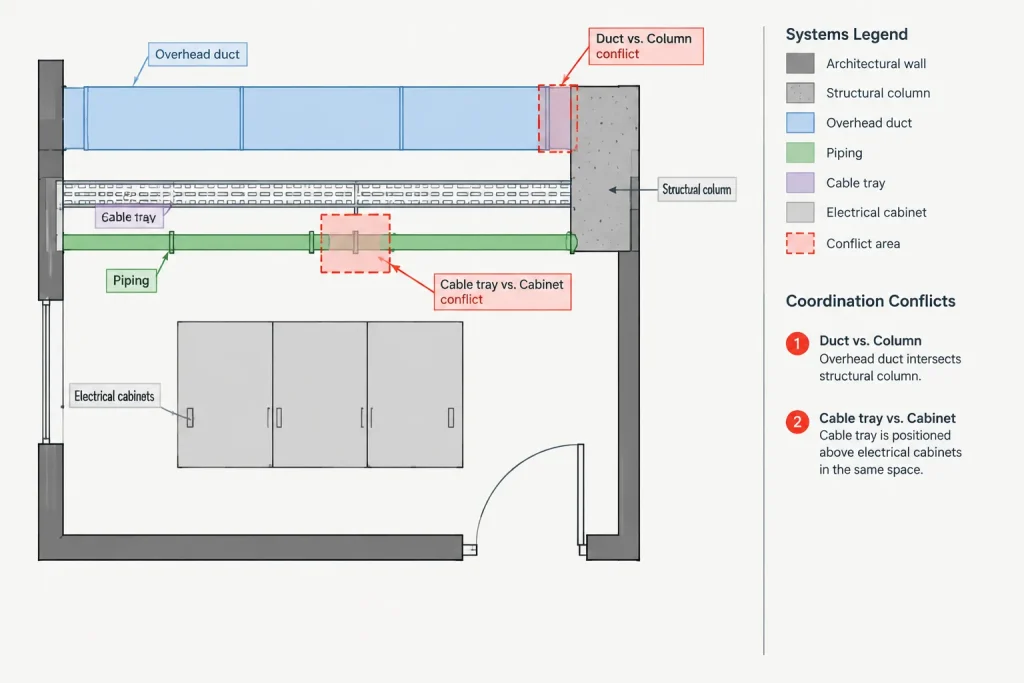
Electrical rooms often attract services that appear minor on other discipline plans but create significant conflicts in the room. Coordination reviews should consider structural framing, piping, ducts, drains, ceiling elements, fire protection components, security devices, and architectural hardware.
Use discipline overlays to look for:
- Services crossing equipment access zones
- Door swings obstructed by equipment or cabinets
- Columns or wall offsets reducing usable space
- Overhead systems occupying pathway entry zones
- Floor openings misaligned with equipment connection areas
- Equipment tags or dimensions obscured by background graphics
- Conflicts between wall-mounted devices and larger equipment
Record unresolved items in a coordination log rather than hiding them with graphic adjustments. Moving a label may improve readability, but it does not resolve a physical conflict.
Use Dimensions Selectively
Dimensions should establish design intent without turning the electrical plan into a duplicate architectural dimension plan. Dimension equipment from stable references such as structural grids, finished wall faces, or other project-defined control points.
Avoid chained dimensions that depend on several unverified equipment widths. If a footprint changes, the entire chain may become misleading. Also avoid dimensioning directly from an external reference if the dimension will not update or be reviewed when that reference changes.
Dimensions should be supported by equipment tags and schedules. The plan identifies the object and location; the schedule or verified equipment data identifies what the object represents.
Connect the Layout to the Drawing Set
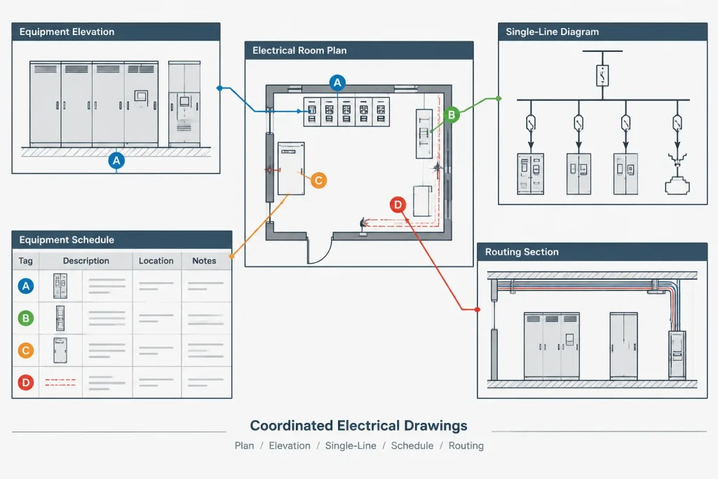
The same equipment identifier should appear consistently on the room plan, single-line diagram, schedules, feeder information, elevations, details, and related control drawings. Similar-looking equipment should not be identified only by graphic appearance.
Useful cross-references may include:
- Section or elevation markers for vertical arrangement
- Detail references for equipment bases or penetrations
- Single-line references for electrical system relationships
- Schedule references for equipment descriptions
- Feeder or raceway tags for route continuity
- Key plan references showing the room’s building location
Cross-references must be checked during each issue. A room plan can retain the correct equipment arrangement while pointing to a renamed or deleted detail.
Perform a Focused Pre-Issue Review
Before publishing the sheet, review the electrical room as a coordinated space rather than checking symbols individually.
- Confirm that the architectural and structural backgrounds are current.
- Verify equipment tags against schedules and diagrams.
- Check footprints against the latest available equipment information.
- Confirm that front and access sides are unambiguous.
- Review access, removal, and routing zones for overlap.
- Check doors, wall-mounted devices, and overhead services.
- Verify pathway entry direction and related drawing references.
- Inspect the plotted output for readable text, hatches, and lineweights.
- Identify preliminary geometry explicitly.
- Track unresolved coordination items outside the drawing markup alone.
An effective electrical room layout makes spatial assumptions visible. By separating verified footprints from preliminary allowances, coordinating access and pathways, and connecting equipment tags across the drawing set, the CAD plan becomes a dependable review tool rather than a simple arrangement sketch.
Improve Layout Reliability with Information Status
A coordinated plan becomes easier to manage when each important object has a recognizable information status. Equipment may be based on verified documentation, a design allowance, or an unresolved coordination requirement. These conditions should not look identical on the issued drawing.
Status can be communicated through layer assignments, block attributes, restrained notes, or a project legend. The method should remain consistent across plans, elevations, schedules, and coordination views. Graphic differences should survive plotting and should not depend on color alone.
Track Responsibility Without Crowding the Plan
The plan should communicate spatial intent, while supporting records can identify where the geometry came from and who must confirm it. Useful block-library or coordination-log fields may describe the equipment source, verification status, responsible discipline, and pending decision. This information helps teams evaluate changes without filling the plotted sheet with administrative notes.
Review Changes by Their Spatial Effect
An equipment revision can affect more than its footprint. Review whether the change alters orientation, access sides, removal paths, support conditions, pathway entry regions, nearby wall devices, or referenced elevations. A block replacement should therefore trigger a coordination review rather than being treated as a purely graphic update.
Use Dedicated Views for Different Review Tasks
A single crowded plan does not need to serve every purpose. Controlled layer states or view configurations can present the same coordinated geometry for different review needs.
- Equipment view: Emphasizes footprints, tags, orientation, and room boundaries.
- Access view: Highlights operational, maintenance, and removal zones.
- Routing view: Emphasizes pathway approaches, entry regions, openings, and vertical transitions.
- Coordination view: Displays relevant structural and building-service overlays for conflict review.
- Issue view: Shows only the information required for the intended drawing package.
These views should derive from controlled geometry rather than separate copies of the room arrangement. Duplicate plans can drift apart when equipment or architectural conditions change.
Check the Layout as a Communication System
Final review should consider how a reader moves through the documents. The room plan identifies physical relationships, the single-line diagram explains system relationships, schedules define equipment identities, and sections or elevations clarify vertical conditions. Matching tags and dependable references connect those documents.
If a condition cannot be understood from the plan, add an appropriate reference or supporting view instead of forcing excessive detail into the room layout. Clear information hierarchy makes uncertainty visible and gives reviewers a practical path to the controlling document.
Frequently Asked Questions
What is the main purpose of an electrical room CAD layout?
Its main purpose is to communicate the intended spatial relationship among equipment, room construction, access areas, pathway interfaces, and other building systems. It also directs readers to related diagrams, schedules, sections, and details.
Should access zones be included inside equipment blocks?
They may be associated with a block, but they should remain independently controllable. Separate layers or visibility settings allow reviewers to isolate access information without changing the equipment footprint.
How should preliminary equipment be shown?
Use a clearly identified placeholder or allowance and distinguish it from verified equipment geometry. The drawing should not present an assumed footprint or connection location as final.
Why are equipment tags important when the blocks look different?
Graphic appearance alone is not a dependable identifier. Tags connect each object to schedules, single-line diagrams, feeder information, elevations, and other documents in the drawing set.
When is an elevation or section preferable to a plan view?
An elevation or section is useful when vertical pathway entry, stacked equipment, overhead services, wall-mounted components, or support interfaces cannot be communicated clearly in plan.
Can a generic electrical equipment block be used for construction coordination?
A generic block can support early planning if its status is explicit. It should not be treated as approved construction geometry until actual dimensions, access needs, installation conditions, and manufacturer information have been verified for the project.











Leave a Reply
You must be logged in to post a comment.