
Receptacle plans in CAD are coordination documents rather than simple collections of outlet symbols. Their usefulness depends on whether device graphics, circuit references, equipment identifiers, mounting context, and architectural relationships can be read together without ambiguity.
The guidance below focuses on building a maintainable drawing system. It explains how to keep symbols consistent, separate device identity from changing circuit data, coordinate receptacles with equipment, and review the completed plan as part of the wider electrical drawing set.
A receptacle plan may look simple, but each symbol can carry several layers of design intent. The drawing must communicate device type, approximate location, circuit association, mounting condition, and any relationship to furniture or equipment. If those elements are handled inconsistently, the plan quickly becomes difficult to review and coordinate.
Good receptacle plans in CAD separate graphic clarity from technical data. Symbols identify devices, tags connect them to circuits or schedules, and notes address conditions that cannot be shown clearly in plan view. This approach produces drawings that are easier to revise without implying unverified installation requirements.
Define the Purpose of the Receptacle Plan
Before placing blocks, determine what the sheet is expected to communicate. Some projects use a dedicated power plan, while others combine receptacles with equipment connections, mechanical power, or additional electrical devices. The drawing organization should reflect the density and complexity of the project rather than a fixed convention.
A receptacle plan commonly documents:
- General-use receptacle locations.
- Receptacles associated with identified equipment.
- Floor, wall, ceiling, or furniture-mounted devices.
- Special device configurations or protection characteristics when required by the project documents.
- Branch-circuit or panel references.
- Controlled, switched, emergency, backup, or other power-source distinctions.
- Existing, new, relocated, and removed devices where renovation scope applies.
The plan should show design intent without becoming a substitute for specifications, schedules, approved product data, or field verification.
Build a Controlled Receptacle Symbol Set
Start with a small, consistent family of CAD blocks. Excessive symbol variation makes the legend harder to use and increases the chance that similar devices will be confused. A new symbol should represent a meaningful drawing distinction, not merely a drafting preference.
Each block should have a predictable insertion point and orientation behavior. For wall-mounted symbols, an insertion point at the intended wall contact location can make placement and rotation more consistent. Floor and ceiling device blocks may need a centered insertion point. The correct choice depends on how the symbol is used across the drawing set.
Useful block distinctions may include mounting location, device configuration, power source, or another project-defined characteristic. Avoid encoding too much information through tiny linework. If a difference will not remain visible at the plotted scale, use a readable tag, abbreviation, or keynote instead.
Keep Similar Symbols Visually Related
A symbol family should look like a family. Related receptacles can share a recognizable base graphic, with limited modifiers used to show documented differences. This helps readers understand unfamiliar variants by comparing them with the legend.
Do not assume that a familiar-looking symbol has a universal meaning. Symbol practices vary among offices, clients, and project types. Define every project-specific symbol in the legend and verify imported blocks before use.
Separate Device Identity from Circuit Information
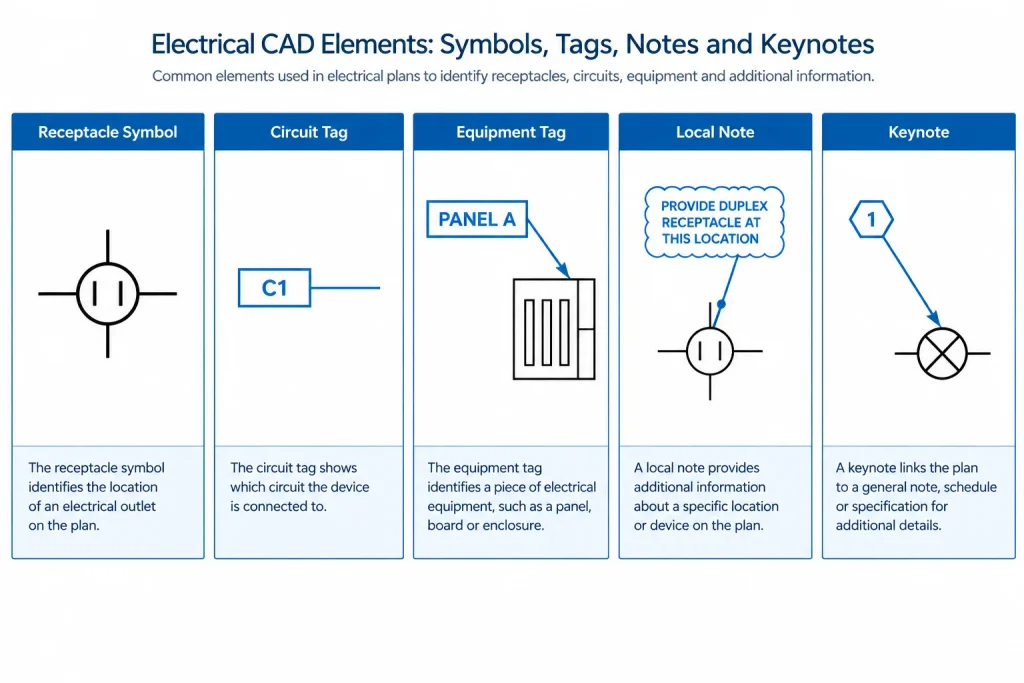
The receptacle symbol identifies the device condition; the circuit tag identifies its electrical relationship. Combining both into one static block often creates revision problems. A circuit reassignment should not require replacing the underlying device symbol.
Circuit information may be shown with nearby text, attributed blocks, leaders, or circuiting linework. Whichever method is selected, apply it consistently. A reader should not have to guess whether a label refers to one receptacle, a group of receptacles, or nearby equipment.
| Drawing element | Primary purpose | Coordination concern |
|---|---|---|
| Receptacle symbol | Shows device type and plan location | Must match the legend and mounting context |
| Circuit tag | References a panel and circuit assignment | Must agree with panel documentation |
| Equipment tag | Links the outlet to a named load or equipment item | Must match equipment plans and schedules |
| Local note | Describes a condition unique to one location | Should point clearly to its intended object |
| Keynote | References repeated instructions | Must remain coordinated with the keynote list |
Place Symbols Using the Architectural Background
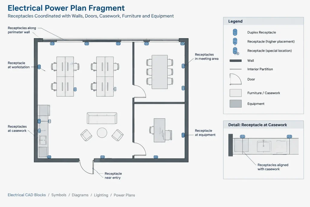
Receptacle placement should respond to walls, casework, doors, glazing, furniture, and equipment rather than forming an arbitrary graphic pattern. Use the architectural background as a controlled reference, but do not treat every background line as verified installation information.
When locating symbols, review:
- Which side of a wall or partition the device serves.
- Whether the symbol conflicts with door swings, built-in casework, or glazing.
- Whether furniture or equipment could conceal the device.
- Whether the intended mounting surface is clearly identifiable.
- Whether nearby devices are separate or part of a grouped assembly.
- Whether an enlarged plan or elevation provides more precise information.
A plan symbol normally communicates a horizontal relationship more effectively than an exact vertical position. When mounting height or alignment is important, coordinate the plan with an elevation, schedule, detail, or project note. Avoid placing dense height text beside every device when a controlled reference can communicate the information more clearly.
Coordinate Receptacles with Equipment
Equipment-related receptacles require more than proximity. The drawing should establish which device serves which equipment item. A nearby symbol may otherwise be interpreted as general-use power.
Use a consistent equipment identifier that can be traced across the power plan, equipment schedule, mechanical or architectural plan, and related details. Where several connections occur in a small area, an enlarged plan or equipment elevation may be clearer than multiple overlapping leaders.
Do not infer connection characteristics from a generic equipment outline. Equipment requirements can change during design and procurement. Keep uncertain information clearly identified for coordination, and update the electrical documents when verified source data becomes available.
Distinguish Receptacles from Other Connection Types
A receptacle, direct connection, disconnect, connection point, and junction box should not be represented interchangeably. Even when they serve similar equipment, they communicate different interfaces. Use the correct symbol category and coordinate it with the one-line diagram, schedule, or equipment connection detail where applicable.
Manage Circuiting Without Obscuring the Plan
Circuiting graphics should explain relationships, not trace an exact concealed wiring path unless the drawing specifically requires routing information. Keep circuiting lines visually subordinate to device symbols and tags. Route them around room names, dimensions, and important architectural features where practical.
For grouped devices, make the circuit association unambiguous. A circuit tag placed between several symbols can be misread if there is no grouping line, leader, or established office convention. Conversely, drawing a separate circuit arc to every device can overload a dense plan. Select the lightest method that still communicates the intended relationship.
Home-run indications and panel references should use the same naming found in panel schedules and distribution drawings. Temporary placeholders should be easy to search for and should not resemble final circuit assignments.

Use Layers and Attributes Deliberately
Organize receptacle graphics so symbols, circuiting, tags, and notes can be managed independently. This allows drafters to adjust visibility for coordination, plotting, or review without editing the device blocks themselves.
A practical layer strategy may separate:
- Device symbols.
- Circuiting or relationship lines.
- Circuit and panel tags.
- Equipment connection annotations.
- Demolition or existing-work graphics.
- Coordination markers that are not intended to plot.
Block attributes can store device IDs, circuit references, or status fields, but visible text should remain readable and logically placed. Hidden attributes can support schedules or audits only when the project team understands how they are maintained. Do not rely on embedded data that no one reviews.
Review the Plan as a Coordinated Document
A CAD file can be geometrically clean and still be technically inconsistent. Review receptacle plans against the legend, schedules, equipment information, architectural background, and related electrical sheets.
Suggested Review Sequence
- Symbol review: Confirm that every placed block has a defined meaning and uses the current library version.
- Location review: Check walls, room boundaries, casework, furniture, doors, and equipment interfaces.
- Tag review: Look for missing, duplicated, overlapping, or ambiguous circuit and equipment labels.
- Schedule review: Compare visible assignments with panel and equipment documentation.
- Status review: Confirm that existing, new, relocated, and removed work is graphically distinct.
- Plot review: Inspect the published sheet at its intended output size rather than relying only on model-space zoom.
Also search for orphaned text and attributes. A receptacle may have been deleted while its circuit label remains, or a symbol may have been moved without its associated note. These errors are often easier to find through a combination of visual review and CAD data checks.
Draft for Change as Well as Initial Clarity
Receptacle plans evolve as room layouts, equipment selections, and circuit assignments change. A maintainable drawing keeps the symbol, technical tag, and explanatory note separate enough to revise without redrawing the entire condition.
The strongest workflow uses standardized blocks, controlled layers, traceable equipment IDs, and a repeatable review process. The result is not merely a neat plan. It is a coordinated document in which each receptacle can be understood in context and checked against the rest of the electrical drawing set.
Use the Plan as a Traceable Information Map
A well-organized receptacle plan allows a reviewer to follow each documented condition from the plan symbol to the related legend, circuit reference, equipment record, note, or detail. When that path breaks, the drawing may remain visually polished while its design intent becomes uncertain.
Traceability is especially important when information comes from different disciplines. An architectural background may establish the room and wall relationship, an equipment schedule may identify the served item, and electrical documentation may define the circuit association. The CAD plan should connect those sources without silently replacing one source with another.
Identify the Authority for Each Type of Information
- Device graphics: Control through the approved project symbol library and legend.
- Room and mounting context: Coordinate with the current architectural background and applicable details.
- Equipment identity: Match the identifiers used by the responsible discipline and related schedules.
- Circuit association: Reconcile with panel and distribution documentation.
- Special conditions: Reference the appropriate note, schedule, elevation, or detail instead of crowding the plan.
Control Background and Data Changes
Background revisions can move walls, casework, furniture, and equipment without automatically moving electrical symbols. After an updated reference is loaded, review affected spaces by condition rather than checking only whether the reference attached correctly. A symbol that remains in its original coordinates may no longer serve the intended surface or equipment.
Circuit and equipment data require similar change control. If visible tags and stored attributes are maintained separately, define which field is authoritative and include both in review. Otherwise, a drawing can display one assignment while a schedule extraction reports another.
Check Relationships, Not Just Individual Objects
Object-level checks can find missing blocks or empty attributes, but coordination errors often occur between objects. Review the relationship between each receptacle and its wall, associated tag, served equipment, status graphic, and referenced documentation. This approach helps reveal detached labels, outdated identifiers, and symbols that were copied without their supporting information.
Prepare a Clean Issue View
Before publishing, isolate nonplot coordination layers, resolve temporary markers, and confirm that screening and line hierarchy preserve the electrical information over the background. Review the actual sheet composition, including legends, notes, match lines, enlarged views, and referenced details.
The final test is whether another qualified reader can determine what the symbol represents, what it serves, how it is identified, and where supporting information is located. If that interpretation depends on undocumented office knowledge, the plan needs clearer notation or a better legend.
Frequently Asked Questions
What should a receptacle symbol communicate?
The symbol should identify the documented device condition and its approximate plan location. Circuit assignments, equipment relationships, mounting information, and special requirements may be carried by tags, modifiers, notes, schedules, elevations, or details.
Should circuit information be built into the receptacle block?
Keeping circuit data separate from the base symbol usually makes revisions easier. Attributes may still support data management, but the visible assignment and the stored information must remain coordinated.
Does a plan symbol establish an exact mounting position?
A plan view primarily communicates horizontal location and mounting context. Where vertical position or alignment matters, the plan should coordinate with the applicable elevation, detail, schedule, or project note.
How should an equipment receptacle differ from a general-use receptacle?
The documentation should make the equipment relationship explicit through a traceable identifier, leader, note, or other established convention. Proximity alone may not show that a device is dedicated to a particular equipment item.
What should be checked after an architectural background update?
Review device relationships to walls, doors, glazing, casework, furniture, room boundaries, and equipment. Also check whether leaders, tags, notes, and enlarged views still point to the intended conditions.
How can a crowded receptacle plan remain readable?
Use a controlled symbol family, separate annotation layers, concise identifiers, and enlarged views where needed. Avoid adding tiny modifiers or overlapping leaders that will not remain clear in the published sheet.











Leave a Reply
You must be logged in to post a comment.