
Terminal block diagrams in CAD connect schematic intent with documented panel and field wiring references. Their value depends on more than symbol placement: terminal identities, jumper relationships, cable tags, destination references, and continuation notes must remain coordinated throughout the drawing set.
This reference explains how to structure terminal strips as readable, data-centered CAD documentation. It also highlights decisions that affect block libraries, schedules, cross-references, revisions, and quality control without treating the drawing as a substitute for verified equipment information.
Terminal block diagrams document the organized connection points between control panels, field devices, packaged equipment, and external wiring. They may look simple, but a poorly structured diagram can leave reviewers searching through schematics, cable schedules, and vendor drawings to understand where a conductor begins and ends.
In CAD, the objective is not merely to draw rows of terminals. The drawing should create a reliable reference system connecting terminal strips, conductors, cables, devices, and related sheets. A consistent layout also makes revisions easier when terminals are added, removed, reserved, or reassigned.
What a Terminal Block Diagram Communicates
A terminal block diagram is a connection-oriented document. It identifies the terminals in an enclosure and shows how each point relates to internal wiring, external wiring, cables, or connected devices. Depending on project scope, the information may appear in a graphical strip diagram, a tabular terminal schedule, a connection diagram, or a combination of these formats.
A useful terminal drawing commonly communicates:
- The enclosure, cabinet, or panel containing the terminal strip.
- The terminal strip identifier and individual terminal designations.
- The internal and external sides of each connection.
- Associated wire, conductor, or cable identifiers.
- Connected device tags or destination references.
- Jumpers, bridges, shields, grounding points, and spare terminals where applicable.
- Cross-references to schematics, interconnection diagrams, cable schedules, or vendor documents.
The diagram should represent documented design intent rather than imply an installation arrangement that has not been verified. Terminal types, accessories, ratings, and physical configurations must be coordinated with the selected equipment and project requirements.
Choose the Drawing Format Before Building Blocks
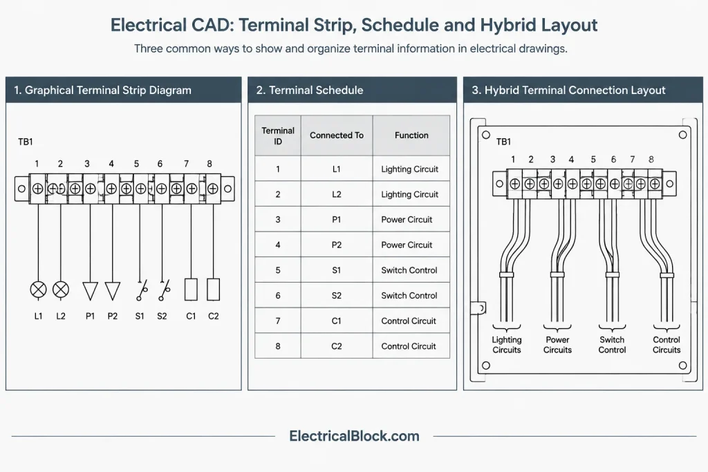
Before creating terminal symbols, determine how the project will use the drawing. A graphical format is effective when users need to see terminal order, jumpers, and connection direction. A schedule format is often more compact and easier to sort. A hybrid format can show the strip graphically while placing detailed cable and destination data in aligned columns.
| Format | Best use | Primary limitation |
|---|---|---|
| Graphical strip diagram | Showing terminal sequence, grouping, and jumper relationships | Can become wide or crowded when connection notes are long |
| Terminal schedule | Managing structured connection data in rows and columns | May not clearly convey physical relationships |
| Hybrid diagram | Combining terminal order with detailed from-to information | Requires careful alignment and data coordination |
Use one primary format for similar enclosures across a drawing set. Mixing unrelated conventions forces readers to relearn the presentation on each sheet.
Establish a Clear Reading Direction
A terminal diagram needs an obvious reading direction. For example, internal panel connections may be shown on one side of the strip and external or field connections on the other. Another project may arrange source information above the terminal and destination information below it. Either method can work if it remains consistent and is explained in the legend or diagram notes.
Use headings such as internal, external, field, or panel only when those terms accurately describe the connection boundary. Avoid relying solely on left and right because a diagram may later be rotated, split, or reused in another sheet layout.
Build a Reusable Terminal Symbol System
A terminal block library should support variation without producing dozens of nearly identical blocks. Start with a small set of controlled symbol types, such as a standard connection terminal, grounding terminal, disconnecting terminal, fused terminal, spare position, and separator. Include specialty symbols only when the drawing must distinguish those functions.
Useful block attributes may include:
- Terminal strip ID.
- Terminal designation.
- Function or signal description.
- Internal wire reference.
- External wire or cable reference.
- Source and destination tags.
- Drawing or grid cross-reference.
- Status, such as active, spare, or future.
Keep attribute locations predictable. Terminal identifiers should remain readable even when connection lines approach from different directions. If a value belongs in a schedule rather than beside the symbol, do not crowd the diagram simply because the block can store it.
Separate Identity from Appearance
The terminal designation is data; the terminal outline is graphics. Treating them separately helps preserve identifiers when symbol graphics are updated. It also supports data extraction and drawing audits without requiring users to interpret linework.
Avoid embedding an entire terminal strip as anonymous text inside one block. Individual terminal records are easier to revise, count, and compare. A grouped strip assembly can still be used for placement, provided its component data remains accessible and controlled.
Document Jumpers Without Hiding Connections
Jumpers or bridges connect multiple terminal positions and must be visually distinct from ordinary conductors. Show the jumper adjacent to the affected terminals rather than passing it through terminal labels or destination text. The graphic should make the connected extent clear, especially when a jumper skips positions or stops before the end of a group.

Do not assume that terminals sharing a common description are automatically jumpered. Conversely, do not use a general note when the exact connected positions can be shown directly. Where a jumper is supplied as part of packaged equipment, distinguish documented vendor scope from project wiring scope.
Coordinate Wire, Cable, and Device References
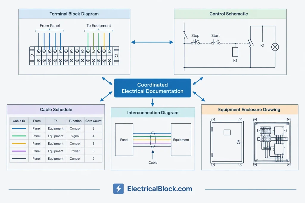
Terminal drawings are most useful when their identifiers match other project documents exactly. A cable ID on the diagram should correspond to the same ID in the cable schedule. A destination equipment tag should match the plan, schematic, equipment list, and interconnection diagram.
A practical connection record may include a from location, from terminal, conductor or cable ID, to location, and to terminal. Not every field must appear graphically, but the information should have one controlled source and a defined update workflow.
Use Cross-References Purposefully
A cross-reference should lead to information that adds context, not merely repeat the same connection. Refer to a schematic when the reader needs circuit function, to an interconnection diagram when the reader needs system boundaries, and to a cable schedule when the reader needs cable-level data.
Choose one cross-reference format and use it consistently. Combining sheet-detail references, drawing-grid references, and free-form notes without a hierarchy makes automated checking difficult.
Organize Layers for Editing and Plotting
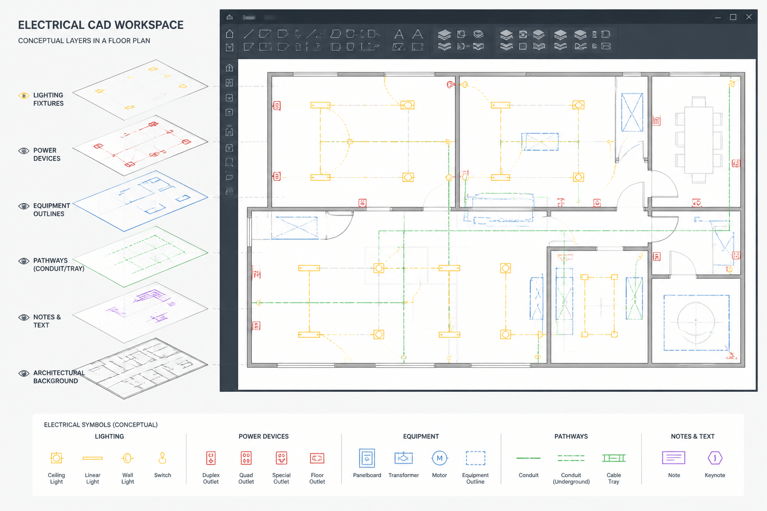
Terminal diagrams benefit from a simple layer structure that separates persistent graphics from connection-specific information. A project may use distinct layers for terminal outlines, internal conductors, external conductors, jumpers, text, cross-references, and revision markup. The exact names should follow the project CAD standard.
Layer separation should support useful tasks: isolating field connections, screening background graphics, checking jumper extents, or plotting revision overlays. Avoid creating a unique layer for every terminal strip unless there is a documented management reason.
Handle Spares, Reserves, and Deleted Positions Carefully
Unused positions should not be left ambiguous. A blank terminal may be mistaken for missing data. Identify whether the position is spare, reserved for a defined function, future, or intentionally omitted. These terms are not interchangeable, so their meanings should be established in the project legend or documentation criteria.
When revising a strip, consider whether renumbering existing terminals would disrupt wire labels, vendor references, or record information. Preserving established identifiers and adding a new position may be clearer than silently shifting every downstream designation. The appropriate choice depends on project status and coordination requirements.
Manage Long Strips Across Sheets
A long terminal strip may need to continue in another column or on another sheet. Add explicit continuation markers showing the strip ID and the next location. Repeat column headings after each break so that internal and external connection sides remain clear.
Do not split a jumper group without a continuation indication. Also avoid placing the terminal strip title only at the beginning of a multi-sheet sequence. Each sheet should provide enough context to identify the enclosure and strip independently.
CAD Quality-Control Checklist
- Confirm that every terminal has a unique and readable designation.
- Verify that strip IDs match enclosure drawings and equipment references.
- Check that internal and external connection sides are clearly labeled.
- Compare wire and cable IDs with the applicable schedules.
- Review jumper start, end, and skipped positions.
- Check that device tags and terminal references exist on related drawings.
- Identify spare, future, and reserved positions consistently.
- Confirm that continuation references work in both directions.
- Look for overlapping text, disconnected lines, and duplicate attributes.
- Plot the sheet at its intended output size and review legibility.
A Data-First Drafting Workflow
Begin by collecting the enclosure list, terminal strip designations, cable records, and relevant schematic connections. Establish the diagram format and reading direction before placing symbols. Build the strip sequence from controlled terminal blocks, then add connection lines, jumpers, destinations, and cross-references.
After the first drafting pass, reconcile the diagram against both the functional schematic and the physical enclosure documentation. Finally, review attribute data and plotted output separately. A drawing can look correct while containing inconsistent hidden values, and a data-complete drawing can still be difficult to read.
Well-structured terminal block diagrams in CAD provide more than a picture of a strip. They form a traceable connection index between panels, cables, devices, and functional drawings. Consistent symbols, controlled identifiers, and deliberate cross-references turn that index into a dependable part of the electrical documentation set.
Distinguish Logical Connections from Physical Arrangement
A terminal block diagram may show connection sequence without representing the exact installed spacing or accessory arrangement. Unless the drawing is specifically defined as a physical layout, readers should not infer mounting order, enclosure clearances, terminal construction, or hardware selection from simplified symbols.
Use drawing titles, notes, and legends to clarify the document’s purpose. Physical arrangement should be coordinated with approved enclosure information and selected terminal components, while functional relationships should be checked against schematics and connection records.
Define Ownership of Connection Data
Duplicate information becomes unreliable when separate drawings are edited independently. The project team should identify which document or managed dataset controls each terminal designation, wire reference, cable identifier, device destination, and status description.
Other drawings can display the same information, but the update process should make discrepancies visible. Attribute extraction, schedule comparison, and structured review can help identify missing records or conflicting identifiers without relying only on visual inspection.
Review the Drawing from Different User Perspectives
A drafter may focus on blocks, layers, and attributes, while a reviewer may need to trace a connection across several documents. A useful review therefore considers both CAD construction and information retrieval.
- Strip review: Check sequence, identity, grouping, continuation, and status.
- Connection review: Trace each documented origin and destination through the applicable references.
- Jumper review: Confirm that graphical extents communicate exactly which positions are connected.
- Coordination review: Compare enclosure names, device tags, wire identifiers, and cable identifiers with related documents.
- Plot review: Confirm that linework, labels, and connection boundaries remain understandable in the issued output.
Preserve Meaning During Revisions
Revision clouds or markup can show where a drawing changed, but they do not explain how related data was affected. When a terminal is inserted, removed, reassigned, or marked for future use, review connected wire records, cable schedules, schematic references, and continuation locations as part of the same change.
Retaining established identifiers can reduce coordination problems, but identifier decisions should follow the project’s document-control process. Never conceal a deleted or unavailable position by shifting labels without reviewing downstream references.
Frequently Asked Questions
Is a terminal block diagram the same as a terminal strip layout?
Not always. A terminal block diagram primarily communicates connections and references. A terminal strip layout may emphasize physical order, accessories, mounting relationships, or enclosure arrangement. The drawing title and notes should state which interpretation applies.
Should every terminal be represented by an individual CAD block?
Individual data-bearing symbols often make terminals easier to edit, audit, and extract into schedules. A grouped assembly can still support efficient placement if the terminal identities and attributes remain accessible rather than being reduced to anonymous graphics.
How should jumpers differ from ordinary conductors?
Jumpers should use a consistent graphical convention that clearly shows their start, end, and any skipped positions. The convention should be identified in the legend and should not obscure terminal labels or connection text.
What is the difference between a spare and a reserved terminal?
A spare is generally an unused available position, while a reserved terminal is being held for an identified purpose. Because project terminology can vary, each status should be defined in the drawing legend or documentation criteria.
Can a schedule replace a graphical terminal diagram?
A schedule can be effective when structured connection data is the priority. A graphical diagram is often clearer for terminal sequence and jumper relationships. The appropriate format depends on how users need to review and coordinate the information.
What should be checked when a terminal strip continues onto another sheet?
Verify the strip identity, enclosure context, reading direction, repeated headings, continuation destination, and return reference. Jumper groups and connection relationships should remain unambiguous across the break.
Leave a Reply
You must be logged in to post a comment.