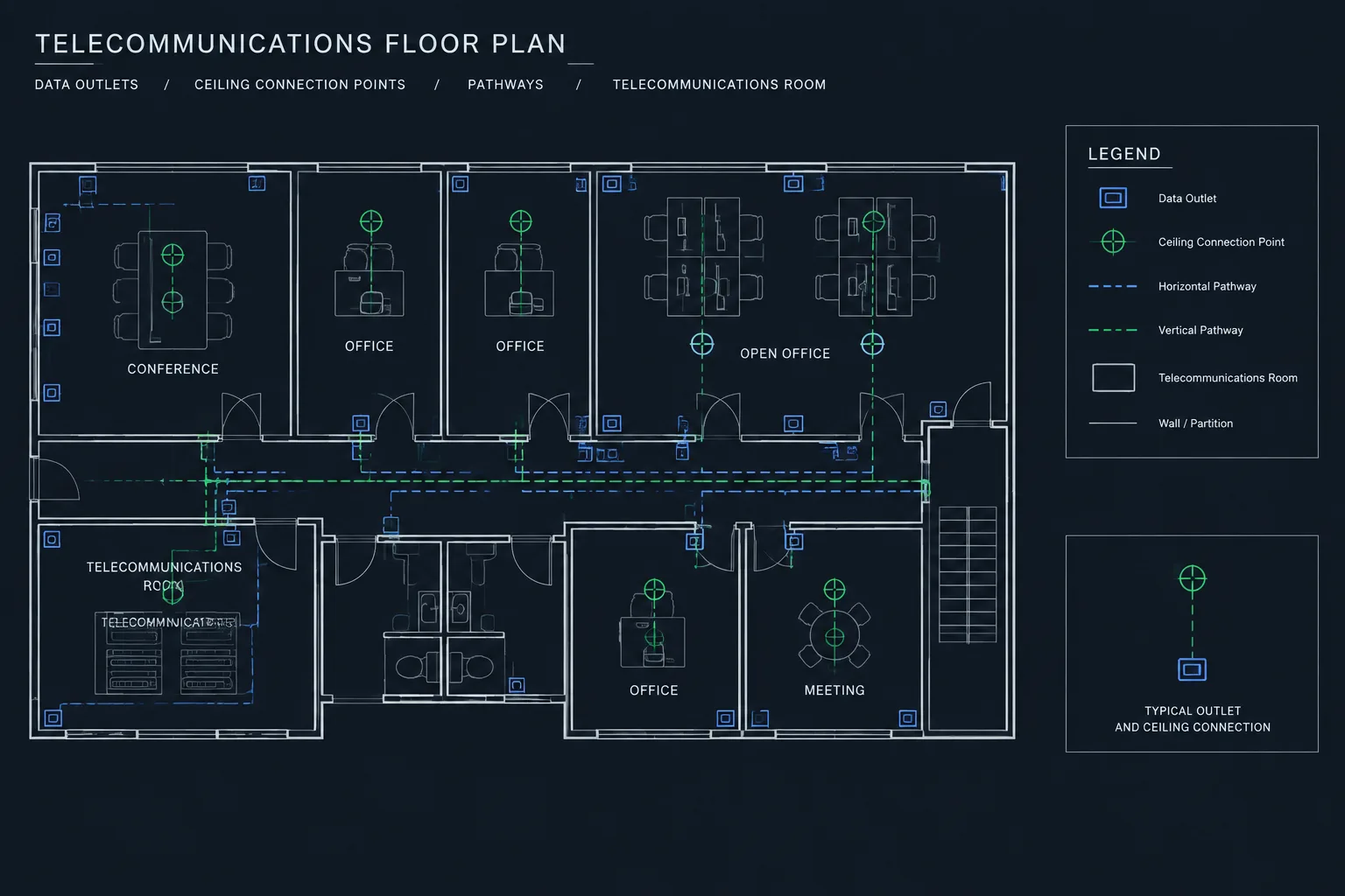
Drafting telecommunications and data plans in CAD requires a coordinated system of symbols, tags, pathways, schedules, and drawing references. The goal is to show where communication services connect while keeping verified requirements separate from assumptions.
This guide explains how to structure a readable plan, relate device locations to architectural conditions, coordinate floor plans with rooms and diagrams, and maintain drawing data through revisions. It focuses on documentation workflow rather than prescribing equipment, cable performance, or installation methods.
Telecommunications and data plans document where communications outlets, pathways, cabinets, rooms, and related connection points belong within a project. Although these drawings often share an architectural background with electrical power plans, they require their own symbol system, tagging logic, schedules, and coordination workflow.
A useful CAD plan should communicate more than the location of an outlet symbol. It should help the project team understand the outlet type, intended service, serving room or cabinet, pathway relationship, and associated schedule or diagram. The plan must remain readable without implying cable quantities, performance categories, or installation requirements that have not been verified for the project.
Define the Drawing Scope Before Placing Symbols
Telecommunications drawings vary considerably by project. Some sets show only outlet locations and general pathways. Others include equipment-room layouts, backbone diagrams, cable schedules, rack elevations, security interfaces, wireless device locations, and audiovisual connections.
Before drafting, establish which systems are included and which are documented by another discipline, consultant, vendor, or deferred package. Possible plan content includes:
- Voice and data outlets
- Wireless access point locations
- Telecommunications rooms and equipment cabinets
- Backbone and horizontal pathway routes
- Conduit, cable tray, sleeves, and pull-box references
- Wall-mounted displays, audiovisual outlets, and floor service points
- Security, access control, or surveillance interfaces
- Service-provider entrance points
- Grounding or bonding references shown elsewhere in the drawing set
Do not combine every low-voltage system onto one plan merely because the geometry fits. Separate plans may be clearer when systems use different symbols, responsibility boundaries, or documentation conventions.
Build a Controlled Symbol Vocabulary
Start with a small, deliberate symbol library. Symbols should be visually distinct at the intended plotted scale and should carry only information that can be maintained consistently.
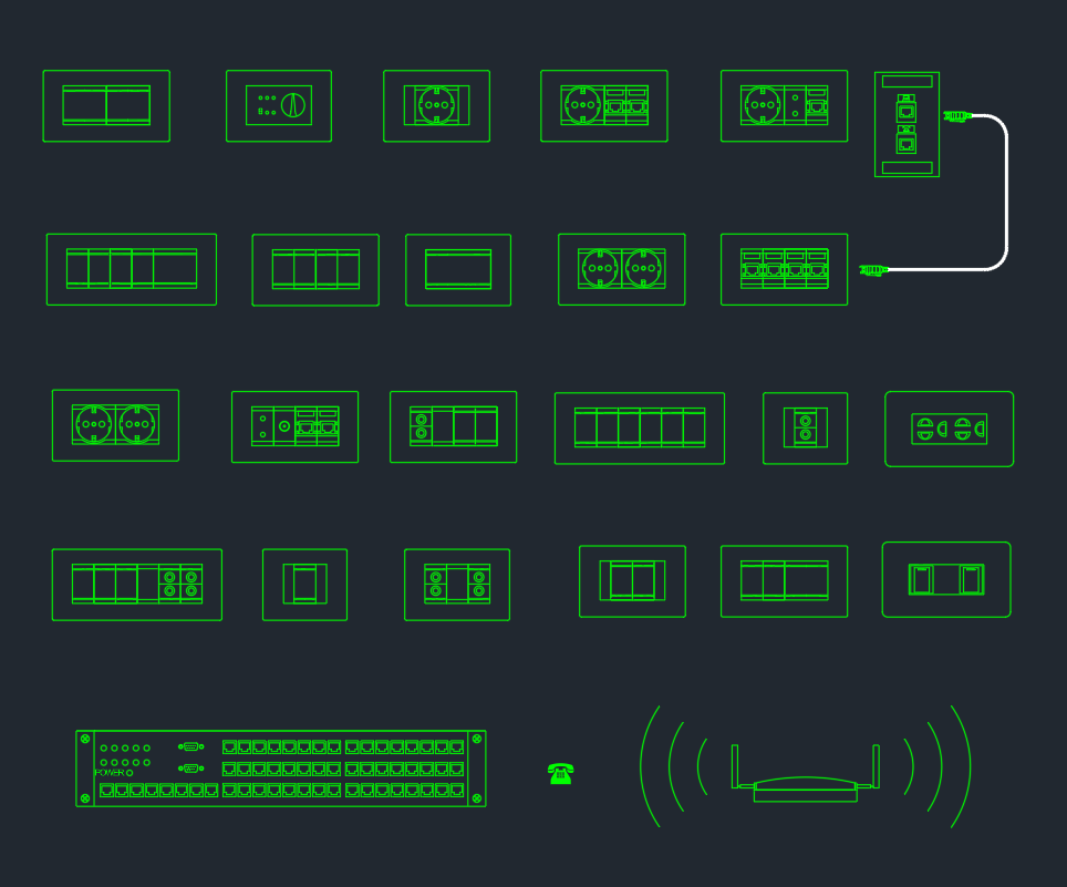
A generic telecommunications outlet symbol, for example, may use an attribute or adjacent tag to identify its configuration. Variations can represent wall outlets, floor outlets, ceiling connection points, furniture feeds, or specialty service locations. The exact graphics are less important than consistent use and a matching legend.
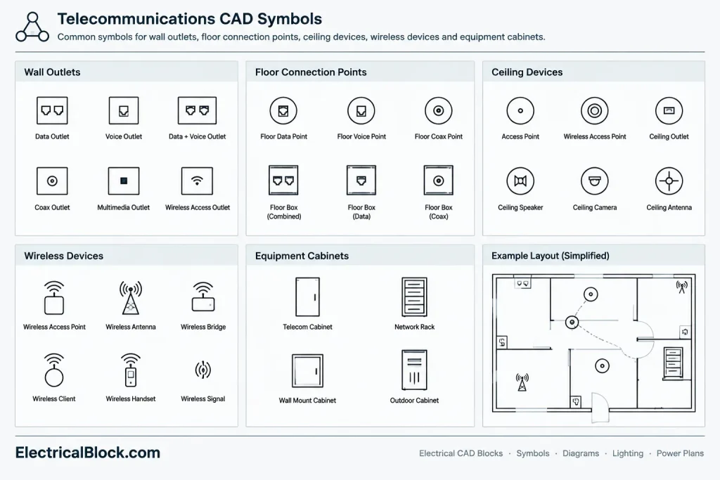
Useful Symbol Attributes
- Outlet or device identifier
- Service or configuration code
- Serving telecommunications room
- Faceplate or connection-point reference
- Mounting condition when it cannot be inferred from the plan
- Schedule, elevation, or detail reference
- Existing, new, relocated, or removed status
Avoid embedding unverified cable performance, connector, manufacturer, or installation information into a generic block. Project-specific requirements should come from the approved design criteria, specifications, schedules, or consultant documentation.
Organize CAD Layers by Information Purpose
Layer organization should allow the drafter to isolate symbols, pathways, text, and references without breaking the drawing. A practical structure separates graphical elements according to how they are reviewed and plotted.
| Layer group | Typical content | Coordination purpose |
|---|---|---|
| Devices | Outlets, wireless devices, cabinets, and specialty connection points | Location and room-by-room review |
| Pathways | Tray, conduit, sleeves, and routing-intent linework | Above-ceiling and structural coordination |
| Tags | Device IDs, room references, and service codes | Schedule and database reconciliation |
| Diagram references | Backbone, riser, detail, or elevation callouts | Navigation between drawing types |
| Coverage or coordination zones | Non-construction coverage graphics and review areas | Design review without obscuring final plans |
| Demolition or existing work | Existing devices, abandoned items, and removal scope | Renovation status control |
Layer names should follow the project CAD standard. The goal is not to impose a universal naming format, but to make each category easy to display, freeze, screen, and audit.
Place Devices Using Architectural Context
Telecommunications outlets are closely tied to furniture, room use, casework, partitions, ceilings, and equipment. Placement should therefore begin with a coordinated architectural background rather than an isolated symbol layout.
Review room names, door swings, built-in furniture, reflected ceiling information, and enlarged plans before finalizing device locations. An outlet placed correctly against an early wall layout can become unusable after a casework or furniture revision.
When a symbol must be offset for readability, use a leader or another documented convention so the actual connection point remains unambiguous. Avoid placing symbols in open floor areas unless the drawing clearly identifies a floor box, poke-through device, furniture connection, or other appropriate condition.
Show Pathway Intent Without Overstating Routing
Pathway graphics should distinguish between an actual coordinated route and a conceptual connection. A line drawn between an outlet and a room can be mistaken for a precise cable or conduit path if its meaning is not defined.
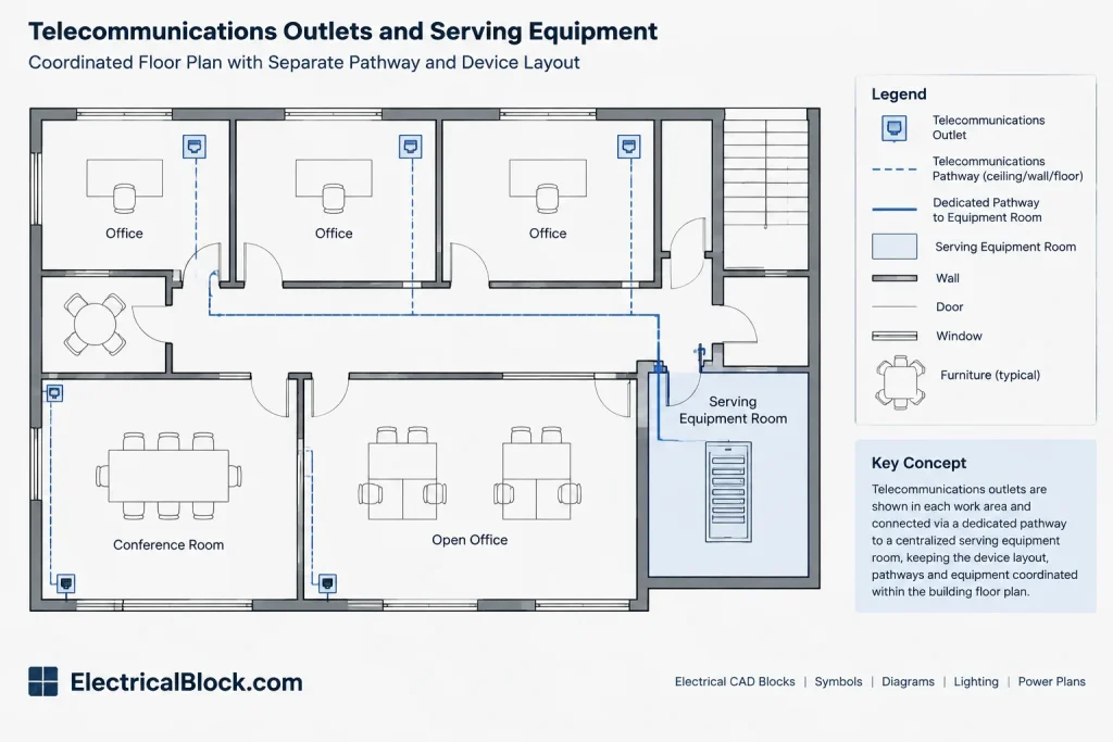
Use notes, linetypes, tags, or legend entries to clarify whether linework represents:
- A dedicated raceway route
- A shared cable tray or pathway
- A conceptual connection to a serving room
- A backbone link shown diagrammatically
- A route requiring further coordination
Pathway plans should be checked against ceilings, structural framing, mechanical systems, access zones, and electrical equipment. Where exact routing is not part of the design scope, document the required endpoints and coordination intent rather than inventing a detailed route.
Coordinate Plans with Rooms, Racks, and Diagrams
A floor-plan symbol should connect logically to the rest of the documentation. If an outlet tag identifies a serving telecommunications room, that room designation should match the equipment-room plan, rack elevation, cable schedule, and backbone diagram.
A reliable drawing relationship is:
- Floor plan: Shows the physical location and plan-level identifier.
- Outlet or device schedule: Defines the intended service or configuration.
- Equipment-room plan: Shows cabinet, rack, board, and pathway locations.
- Rack elevation: Organizes equipment and termination fields where included in scope.
- Backbone or riser diagram: Explains connections between rooms, floors, buildings, or service points.
- Cable schedule: Records from-to information when required by the project.
These drawing types should complement one another rather than repeat conflicting information. For example, the floor plan can identify the serving room while the cable schedule carries the detailed from-to record.
Create a Tagging System That Can Be Audited
Tags should be unique enough to support schedules and revisions, but not so complex that drafters cannot maintain them. A tag may combine a room, zone, device, or service reference, depending on the project workflow.
Before adopting a format, test how it behaves when rooms are renamed, devices are relocated, or project areas are divided among sheets. If changing one room number requires manual edits in several unrelated tags, the system may be too dependent on architectural data.

Block attributes can support consistent identification and extraction, but visible text and stored data must remain synchronized. A hidden attribute should not contradict the label that appears on the plotted plan.
Develop a Clear Legend and General Notes
The legend should show every symbol variant actually used on the drawings. Remove unused symbols inherited from templates, because they create uncertainty about project scope.
General notes should explain drawing-wide conventions such as symbol location meaning, pathway representation, tag composition, and references to related documents. Notes should not be used to compensate for unclear graphics. If several readers interpret a symbol differently, revise the symbol or legend rather than adding layers of explanatory text.
Perform a Focused CAD Quality Review
Review telecommunications and data plans as a coordinated documentation system, not as isolated sheets. A practical check includes:
- Confirming that every symbol used on the plan appears in the legend
- Finding duplicate, missing, or placeholder device tags
- Comparing room and cabinet identifiers across plans and diagrams
- Checking outlets against current walls, furniture, casework, and ceilings
- Verifying that floor devices and ceiling devices use distinguishable graphics
- Reviewing pathway linework for false connections and ambiguous crossings
- Confirming that demolition and new-work graphics are visually distinct
- Checking that references point to existing sheets, details, or schedules
- Plotting at the intended sheet scale to evaluate text and symbol readability
- Removing obsolete blocks, notes, and schedule rows after revisions
Keep the CAD File Useful Beyond the Plot
A well-structured telecommunications plan supports coordination, quantity review, schedule creation, and future revision. Preserve block definitions where practical, use consistent attributes, and avoid replacing structured symbols with disconnected lines and text.
Before issue, verify all project-specific requirements with the responsible design team and applicable project documents. CAD blocks and generic drafting conventions are communication tools; they do not establish cable performance, pathway capacity, system compliance, or suitability for a particular installation on their own.
Prepare the Plan for Review and Issue
Before issuing the drawing, review both the plotted sheet and the underlying CAD information. A plan can appear correct on paper while still containing duplicate block identifiers, outdated attributes, hidden objects, or references to superseded backgrounds.
Confirm that external references use the approved architectural files and that visible room names agree with the identifiers used in tags and schedules. Check layer states in each sheet view so that required devices, pathways, notes, and status graphics are not unintentionally hidden. If structured block data will be extracted, compare the resulting list with the visible plan rather than assuming every block has been completed correctly.
Document Assumptions and Responsibility Boundaries
Telecommunications drawings often depend on information supplied by architects, consultants, equipment vendors, service providers, and facility representatives. Clearly distinguish confirmed design information from coordination placeholders. An unresolved endpoint, pathway, or equipment location should be marked for review instead of being presented as a finalized condition.
Responsibility notes should identify where related information is documented without attempting to replace the governing project documents. This helps prevent a generic CAD symbol or conceptual line from being interpreted as a complete installation requirement.
Manage Revisions Without Losing Drawing Relationships
When devices move or room names change, review every connected record. The plan symbol, visible tag, stored block attributes, schedule entry, serving-room reference, and related diagram may all require attention. Revision review should focus on relationships, not only on highlighted graphics.
Maintain a repeatable check between plans, schedules, equipment-room drawings, and diagrams. This makes telecommunications and data plans easier to audit, coordinate, and update throughout the documentation process.
Frequently Asked Questions
Should telecommunications symbols be placed on the electrical power plan?
They may share the same architectural background, but separate plans are often clearer when the systems use different legends, tags, pathways, or responsibility boundaries. The drawing organization should follow the project documentation plan.
What information should a telecommunications outlet tag contain?
A tag should contain only information that the project team can maintain reliably. Common concepts include a device identifier, service code, serving room, mounting condition, status, or schedule reference. The exact format should match the project workflow.
How should conceptual pathway lines be shown?
Use a defined linetype, note, tag, or legend entry that distinguishes conceptual connectivity from a coordinated physical route. Endpoints and intent should remain clear without implying details that have not been verified.
Why use attributed CAD blocks for data devices?
Attributed blocks can keep identifiers and schedule data associated with each symbol. They also support review and extraction, provided that stored attributes remain synchronized with the text visible on the plan.
What should be checked after an architectural background update?
Review device relationships to walls, doors, furniture, casework, ceilings, room names, and equipment areas. Also check leaders, pathway endpoints, tags, sheet references, and any schedule records affected by the revision.
Can a generic CAD block define the required cable or connector?
No. A generic symbol communicates drawing intent but does not establish project-specific performance, product, or installation requirements. Those requirements must come from verified design criteria and project documents.


Leave a Reply
You must be logged in to post a comment.