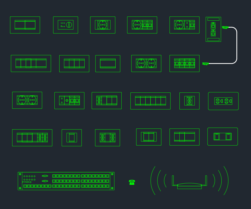
This page provides sockets switches CAD blocks for use in electrical drawing workflows. In United States documentation, a socket may also be described as a receptacle, while switch symbols commonly identify lighting or control locations. Terminology and symbol appearance can vary between drafting standards, offices, and projects.
Before incorporating any downloaded block into a drawing set, compare its geometry and meaning with the project symbol legend. Confirm insertion units, layer behavior, line visibility, block naming, and annotation requirements rather than assuming that a familiar-looking symbol has the intended definition.
Discover high-quality Sockets Switches DWG files and CAD Blocks, perfect for architects, engineers, and interior designers working on electrical layout designs. These detailed CAD Blocks feature various types of sockets and switches, making them ideal for residential, commercial, and industrial projects. The DWG file is fully compatible with AutoCAD and other popular CAD software, ensuring seamless integration into your design workflow. Easily customize and incorporate these sockets switches blocks into your floor plans to streamline the electrical planning process and enhance project accuracy. Download now for efficient and professional electrical designs.
Please log in or register to download this file.
Using Socket and Switch Blocks in Electrical Plans
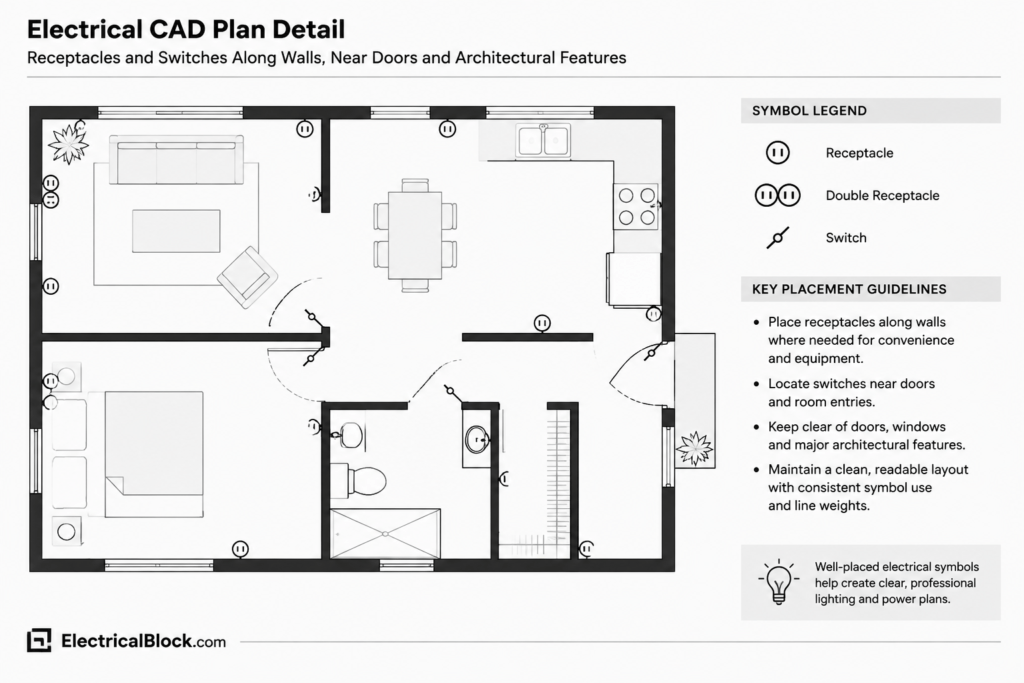
Socket and switch symbols help communicate device locations without drawing the physical equipment in detail. Receptacle-related blocks are commonly coordinated with power plans, while switch blocks are often coordinated with lighting plans and control information. The exact drawing placement depends on the project documentation method.
Place symbols consistently in relation to walls, doors, casework, equipment, and architectural backgrounds. A clear plan should make each device location readable without allowing the block geometry to obscure nearby dimensions, room labels, or other electrical annotations.
CAD Block Review Checklist
- Symbol meaning: Compare the block with the electrical legend and confirm that it represents the intended device.
- Drawing units: Check how the block appears after insertion into the destination file.
- Base point: Confirm that the insertion point supports accurate placement and alignment.
- Layers: Move or map block content to the appropriate project layers when required by the CAD standard.
- Line visibility: Review color, linetype, and lineweight behavior in both model space and plotted output.
- Block names: Use clear names that distinguish device types and reduce conflicts with blocks already present in the drawing.
- Attributes: Check whether identifiers or notes are plain text, attributes, or separate annotations.
- Coordination: Compare device symbols with architectural backgrounds, lighting layouts, equipment plans, and drawing notes.
Organizing Symbols for a Reusable CAD Library
Keep an unchanged source copy of downloaded content before adapting it to an office or project library. Edited blocks can then be renamed, assigned to approved layers, and matched to the project legend without losing the original reference file.
A practical library structure separates receptacle symbols, switch symbols, lighting symbols, equipment symbols, and general annotations. Consistent naming also makes it easier to locate related electrical CAD blocks and maintain uniform documentation across multiple drawing sheets.
Legend and Annotation Coordination
A CAD symbol alone does not communicate every design requirement. Device type, control intent, special conditions, and circuit relationships may depend on tags, notes, schedules, or connecting graphics elsewhere in the drawing set. Keep those references coordinated whenever a block is copied, renamed, or replaced.
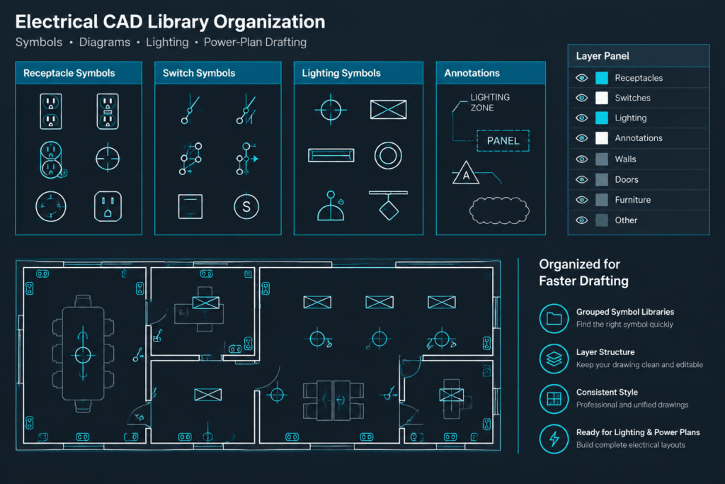
For broader drafting context, review related material on electrical symbol legends, power plans, lighting plans, CAD layers, panel and distribution drawings, and equipment layouts. These topics help place individual socket and switch blocks within a complete documentation workflow.
Final Drawing Review
Inspect the completed layout at the intended plotting scale and review it with the applicable project documents. Check for duplicate symbols, inconsistent orientations, hidden annotations, unresolved block names, and conflicts with architectural elements. Final device selection, design intent, and compliance should be verified by the responsible project professional.
Frequently Asked Questions
What is the difference between a socket and a receptacle in CAD drawings?
The terms may be used differently by region or project team. In United States electrical documentation, receptacle is commonly used for the outlet device, while socket may appear in file names, international libraries, or general architectural terminology. The project legend should define the intended meaning.
Can the same switch symbol be used on every electrical plan?
No universal symbol should be assumed without checking the drawing legend. Switch graphics and annotations may distinguish different control functions, device arrangements, or documentation conventions.

What should be checked after inserting a DWG block?
Review insertion units, apparent size, base point, layer assignment, line properties, orientation, block name, and any attached attributes. Also confirm that the symbol remains legible in the plotted drawing.
Should socket and switch blocks be placed on the same CAD layer?
Layer organization depends on the project CAD standard. Separate layers can improve visibility control and editing, while some workflows group related electrical devices. Follow the established layer naming and plotting system for the drawing set.
How should downloaded blocks be customized?
Retain an original copy, then adapt a working copy to match the project legend, layers, naming conventions, and annotation style. Avoid changing the symbol in a way that makes its documented meaning unclear.












Leave a Reply
You must be logged in to post a comment.