
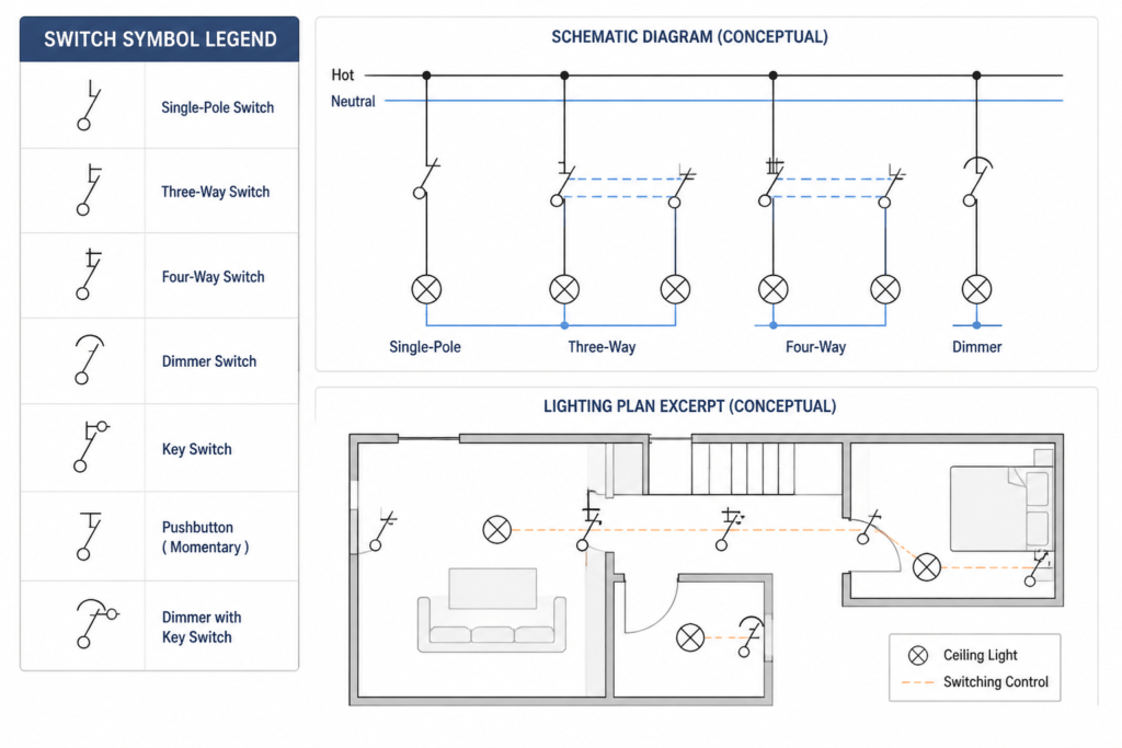
Switch symbols are compact graphic elements that communicate how switching devices are represented on electrical drawings. A well-organized DWG block collection can help drafters maintain consistent notation across lighting plans, power plans, schematic diagrams, and architectural layouts.
This reference explains how to approach switch-symbol blocks in AutoCAD, how to read their role in a drawing, and how to coordinate them with legends, circuit relationships, and drawing layers. The supplied DWG resource should be reviewed within the conventions of the project before it is used in a published drawing.
Discover a high-quality DWG file featuring a comprehensive collection of switch symbols, ideal for architects, electrical engineers, and designers. This CAD Block set includes various standard electrical switch symbols used in schematic diagrams, electrical layouts, and architectural plans. Perfectly compatible with AutoCAD and other leading CAD software, these symbols streamline your drafting process, ensuring accuracy and consistency. Download this DWG file to enhance your projects, save time, and maintain professional standards in all your electrical and architectural designs. Suitable for both residential and commercial applications.
Please log in or register to download this file.
How switch symbols are used in electrical CAD drawings
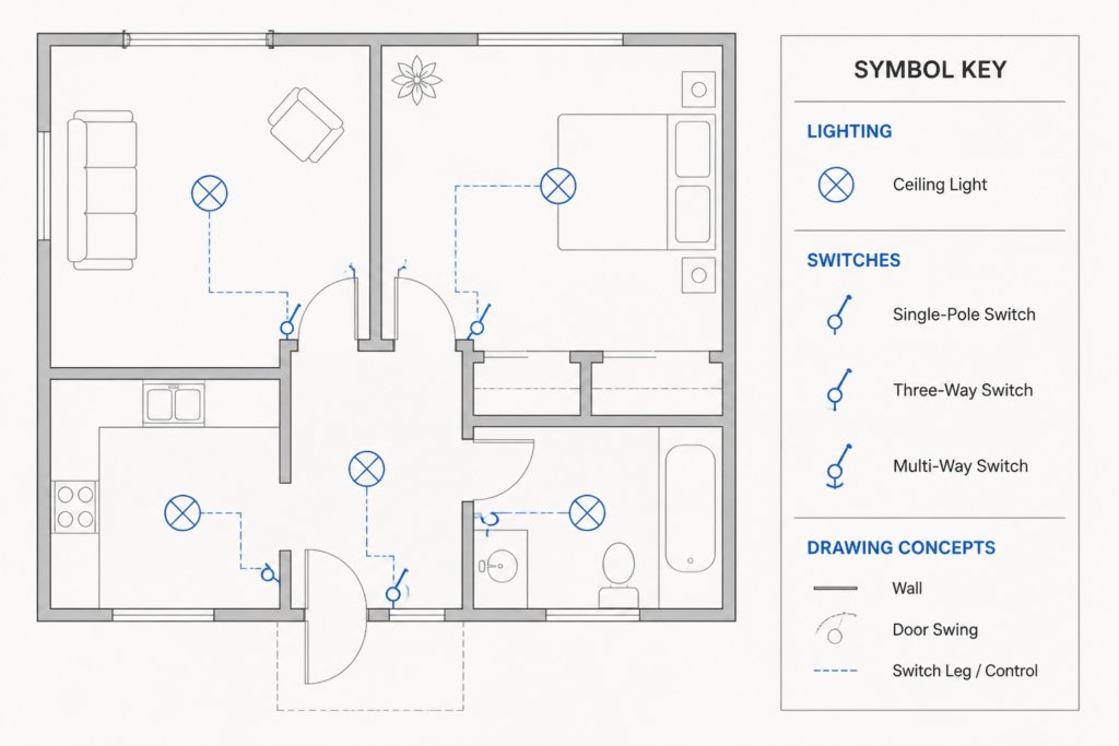
Switch symbols generally identify the control point for a lighting or other electrical function. Their graphic meaning depends on the drawing type, the project legend, and the relationship between the symbol and connected linework. A symbol should therefore be read together with nearby notes, circuit paths, equipment tags, and the applicable drawing key.
Common drawing contexts
- Lighting plans: Switch symbols help show control locations and their relationship to fixtures, rooms, doors, and architectural circulation.
- Electrical schematics: The symbol represents a switching function within a simplified circuit or control diagram.
- Architectural plans: Symbols are coordinated with walls, doors, furniture, reflected ceiling information, and other plan graphics.
- Power and distribution drawings: Switch-related symbols may appear alongside equipment, circuit identifiers, or distribution relationships, depending on the drawing purpose.
CAD coordination checklist
- Confirm that the selected block matches the project symbol legend and drafting standard.
- Check insertion orientation, scale behavior, annotation visibility, and lineweight appearance at the intended print size.
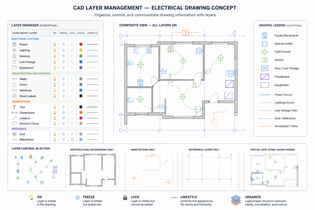
- Place symbols on an appropriate electrical or annotation layer rather than leaving them on an uncontrolled default layer.
- Review block attributes and naming conventions so symbols can be located, edited, and coordinated efficiently.
- Verify that connected linework does not obscure walls, doors, fixture graphics, or room labels.
- Coordinate the drawing representation with the design professional responsible for the electrical documentation.
Using a DWG block collection effectively
A symbol library is most useful when it supports repeatable drafting rather than replacing project-specific review. Before using a block, inspect its geometry, insertion point, layer behavior, attributes, and nested elements. If the collection includes multiple representations, select the version that is clearest for the drawing scale and document type.
For reference work, compare the block against the project legend and distinguish between a graphic symbol, a device tag, and a complete circuit representation. These elements may be related, but they do not communicate the same information. A CAD block also does not by itself confirm installation requirements, circuit design, device selection, or code compliance.
Related electrical drawing concepts
Switch symbols are closely connected to lighting symbols, electrical legends, reflected ceiling plans, single-line diagrams, panel schedules, and cable or conduit drafting. Understanding those relationships makes it easier to trace a drawing from the device symbol to the associated circuit, equipment, or schedule entry without treating the symbol as an isolated graphic.
Frequently asked questions
What is a switch symbol DWG block?
It is a reusable AutoCAD drawing element that represents a switch or switching function in an electrical or architectural drawing. Its exact interpretation should follow the project legend.
Where are switch symbols typically placed?
They may appear on lighting plans, electrical layouts, schematic diagrams, and architectural plans. Placement should reflect the drawing purpose and be coordinated with rooms, doors, fixtures, and connected linework.
Can a switch symbol block be used without checking the drawing legend?
No. Symbol conventions can vary between projects and drafting standards. Review the block against the current legend, layer convention, annotation requirements, and responsible design documentation.
Does a DWG switch block define the complete electrical design?
No. A block is a graphical drafting resource. It does not establish conductor routing, protective-device settings, installation requirements, or design compliance.
What should be checked before inserting a switch block?
Review its geometry, insertion point, orientation, layer behavior, attributes, lineweight, visibility, and coordination with surrounding architectural and electrical graphics.












Leave a Reply
You must be logged in to post a comment.