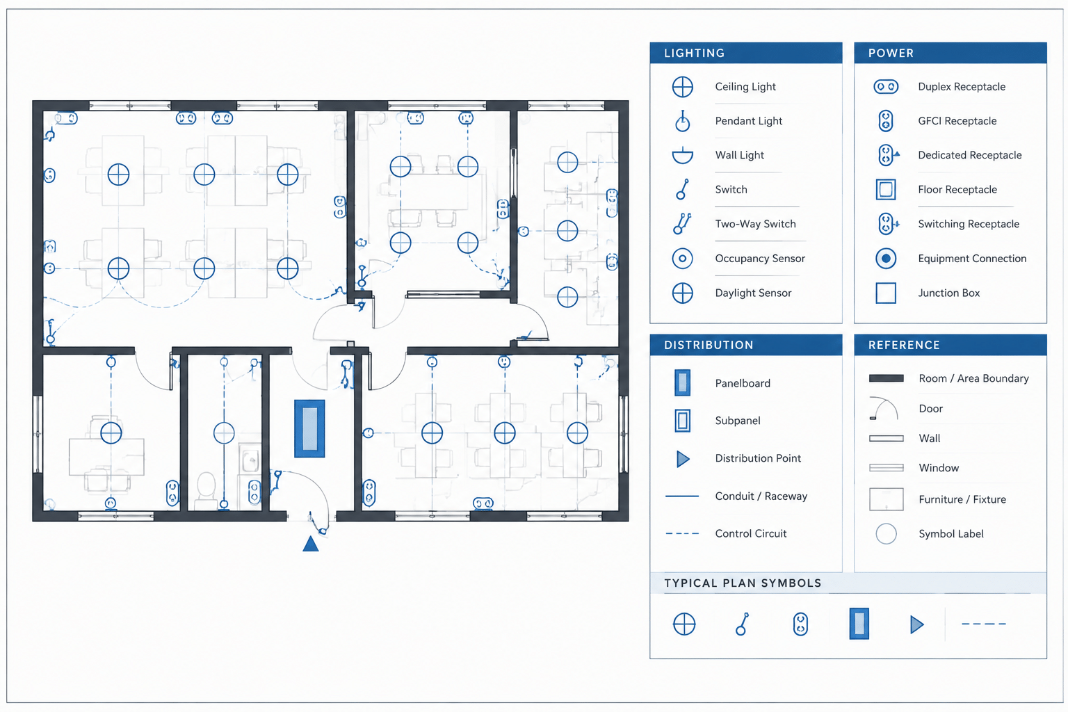
An electrical CAD symbol legend should help a reader interpret the drawings quickly. It should not be a catalog of every electrical block available in the office library. The most useful legends are project-specific, visually consistent with the plans, and coordinated with schedules, notes, diagrams, and detail references.
Creating that result requires more than copying a standard legend into a sheet. Symbols may change as a project develops, blocks may come from several sources, and similar devices may need different tags or graphical treatments. A deliberate legend workflow prevents those differences from becoming drawing conflicts.
What an electrical symbol legend should communicate
A legend connects a graphical mark with its intended drawing meaning. Depending on the document, an entry may include a symbol, a plain-language description, a type identifier, and a note directing the reader to another schedule or detail.
A strong legend answers practical questions such as:
- What does this symbol represent on this project?
- Does a letter or number inside the symbol identify a scheduled type?
- Is the symbol used on a plan, a single-line diagram, a control diagram, or another drawing type?
- Does a graphical variation indicate mounting, connection, control, or another documented condition?
- Where can the reader find additional information?
The legend is not a substitute for design information. Equipment characteristics, circuit assignments, control intent, installation notes, and product requirements generally belong in coordinated schedules, diagrams, specifications, or keyed notes.
Start with the symbols actually used
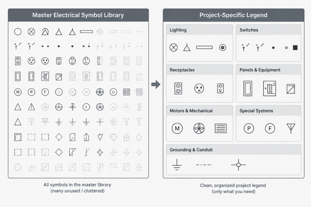
A common drafting problem is the oversized master legend. It may contain dozens of office-standard symbols even though only a small portion appears in the issued set. This makes the reader search through irrelevant entries and can imply that unused device types are part of the project.
Begin with a symbol inventory taken from the current drawings. Review electrical plans, enlarged plans, details, diagrams, and associated schedules. Record each symbol family and any meaningful variants. The inventory should include blocks placed directly in model space as well as symbols nested inside assemblies, typical details, or external references when those symbols are meant to be interpreted by the reader.
For each item, confirm:
- The block name used in the CAD files
- The visible symbol and its rotation behavior
- The project description
- Any attribute, type mark, or schedule identifier
- The drawing types on which it appears
- Whether it is still active, provisional, or obsolete
This inventory creates a practical bridge between the CAD library and the published legend. It also exposes duplicate blocks that look alike but carry different names, or blocks with the same name that display differently in separate files.
Separate symbols by drawing context
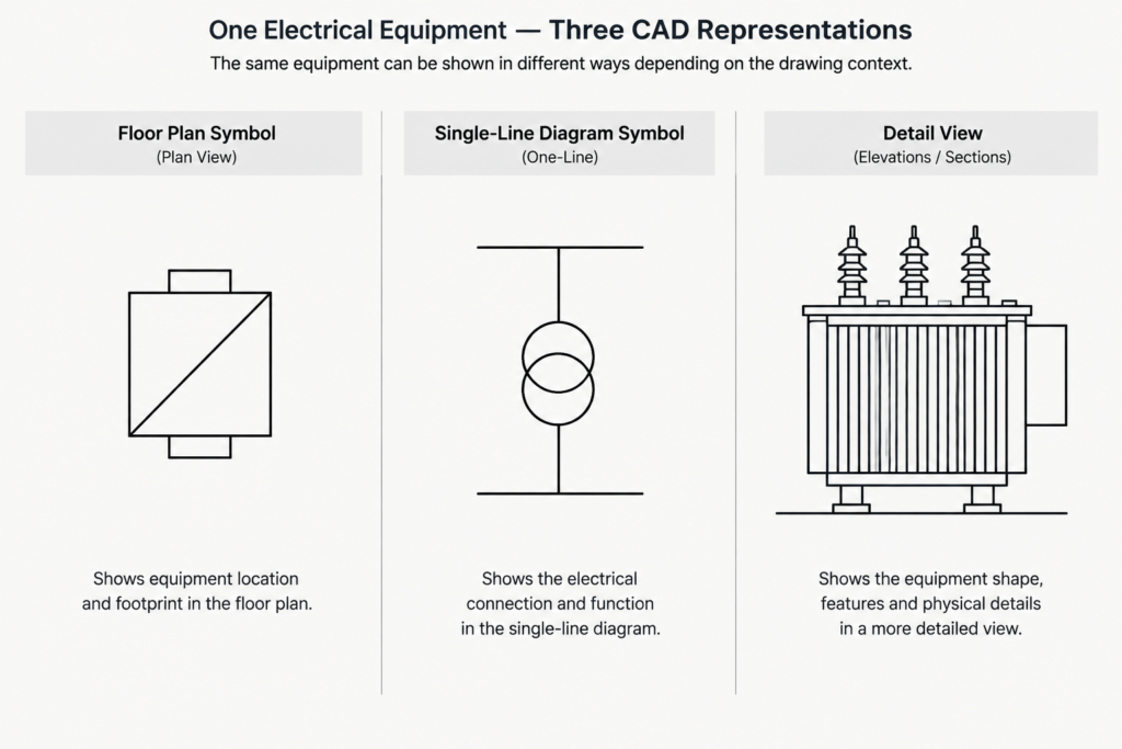
A plan symbol and a schematic symbol may represent related equipment without being graphically interchangeable. Floor plans emphasize location and coordination with the building background. Single-line diagrams emphasize electrical relationships. Control diagrams show functional connections, while details may use simplified or more pictorial representations.
Organize the legend into clear groups when a sheet contains several symbol systems. Typical group headings may include lighting, power devices, distribution equipment, communications, controls, grounding, or diagram symbols. Use only the groups relevant to the project and drawing set.
If the same item is shown differently in different contexts, describe each representation separately. Do not place two unexplained symbols beside one description and assume readers will understand where each applies.
| Legend category | Primary purpose | Coordination target |
|---|---|---|
| Plan symbols | Show device or equipment location | Floor plans, room layouts, mounting notes |
| Diagram symbols | Show system relationships or connectivity | Single-line, riser, and control diagrams |
| Type marks | Connect a symbol to project data | Fixture, equipment, or device schedules |
| Reference graphics | Direct the reader to another view | Details, sections, and enlarged plans |
Control graphical variants carefully
Small graphical changes can carry important meaning, but only when they are used consistently. A filled portion, added line, adjacent letter, or modified enclosure may distinguish one condition from another. If the difference is intentional, the legend must make it visible and understandable at the plotted size.
Avoid creating variants by manually drawing loose geometry over a base block. That approach makes the meaning dependent on several separate objects and allows part of the symbol to be moved or deleted accidentally. A controlled block variant or a documented attribute-driven system is generally easier to audit.
Before adding a variant, ask whether the distinction belongs in the symbol. Information that changes frequently, such as a circuit identifier or equipment type, may be better handled with an attribute or nearby tag. Information that requires a lengthy explanation may belong in a keynote or schedule rather than in increasingly complex symbol graphics.
Match the legend graphics to the plan graphics
The sample shown in the legend should come from the same approved block definition used on the drawings. Redrawing a similar icon inside the legend creates two independent graphic sources that can drift apart.
Check the following characteristics:
- Geometry and orientation
- Linework appearance when plotted
- Visible attributes and attribute positions
- Text style and capitalization
- Layer behavior
- Background masks or wipeout objects
- Readability at the intended sheet presentation
Symbols placed in a legend do not always need the same model-space insertion method as plan symbols, but their published appearance should match. If the legend uses enlarged examples for clarity, make that presentation consistent and avoid suggesting that graphical size represents physical equipment dimensions.
Write descriptions that explain differences
Legend descriptions should be concise, but they need enough detail to distinguish similar entries. Generic labels such as “outlet,” “switch,” or “panel” may not explain why several versions are shown.
Use terminology that agrees with the rest of the documents. If a schedule uses one equipment name and the legend uses another, readers may reasonably wonder whether they refer to different items. Maintain the same naming pattern across block attributes, schedule titles, keynotes, and diagram labels.
Do not embed unverified ratings, construction details, or installation requirements in a reusable symbol description. Project-specific technical information should come from the responsible design documents and be checked for the current application.
Choose between a sheet legend and a general legend sheet
A small project may be easiest to read when each plan sheet includes a compact legend containing only the symbols used there. A larger drawing set may benefit from a central legend sheet, particularly when many sheets share the same symbol system.
Each method has tradeoffs. Sheet-specific legends reduce page turning but can become inconsistent when copied repeatedly. A central legend provides one controlled source but requires readers to navigate away from the plan. Some sets use a hybrid approach: a central project legend plus a short local legend for unusual symbols found only on one sheet.
Whatever method is selected, establish which location is authoritative. Repeated legend entries should not contain conflicting descriptions.
Build a maintainable CAD workflow
Use a controlled source
Maintain the project legend in a clearly identified drawing or sheet file rather than relying on an old plotted document. Office library content can serve as a starting point, but the project copy should be reviewed independently.
Track symbols by meaning, not appearance alone
Two blocks may look identical while serving different documentation purposes. Conversely, two graphical variants may have the same underlying equipment meaning. Record both the block identity and the intended use during quality control.
Coordinate attributes and schedules
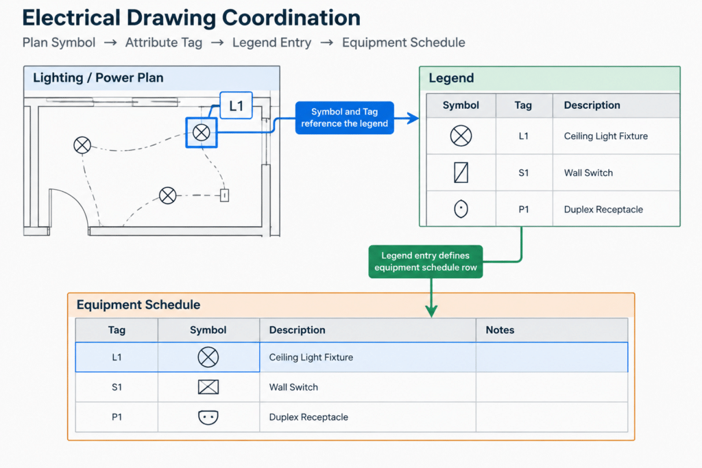
If a symbol displays a type mark, confirm that the mark exists in the corresponding schedule. Check for orphaned schedule rows, duplicate identifiers, and tags that appear on plans without a defined entry.
Remove obsolete entries deliberately
Deleting an unused legend row is only safe after confirming that the symbol no longer appears anywhere in the issue set. Search block references where practical, but also perform a visual review because exploded, nested, or externally referenced graphics may not appear in a simple block count.
Quality-control checklist before issue
- Every legend symbol appears in the project, or its inclusion has a documented reason.
- Every unexplained plan symbol is either added to the legend or clarified elsewhere.
- Legend blocks match the current plan blocks.
- Similar symbols have descriptions that explain their differences.
- Plan, diagram, and reference symbols are separated logically.
- Type marks agree with schedules and drawing tags.
- Descriptions use consistent project terminology.
- Obsolete symbols and notes have been removed.
- The legend remains readable in the issued sheet format.
- No generic library note is presented as project-specific information without review.
A legend is part of the drawing system
An electrical CAD symbol legend works best when treated as coordinated project data rather than decorative sheet content. Its symbols connect to block definitions, its type marks connect to schedules, and its descriptions establish how readers interpret the plans and diagrams.
Keeping the legend limited to relevant content makes it faster to use and easier to maintain. More importantly, matching the legend to the actual drawings reduces ambiguity when symbols are revised, copied, or reused across a multi-sheet set. Any library block or sample legend should still be reviewed for project conventions, drawing context, and the requirements established by the responsible design team.


Leave a Reply
You must be logged in to post a comment.