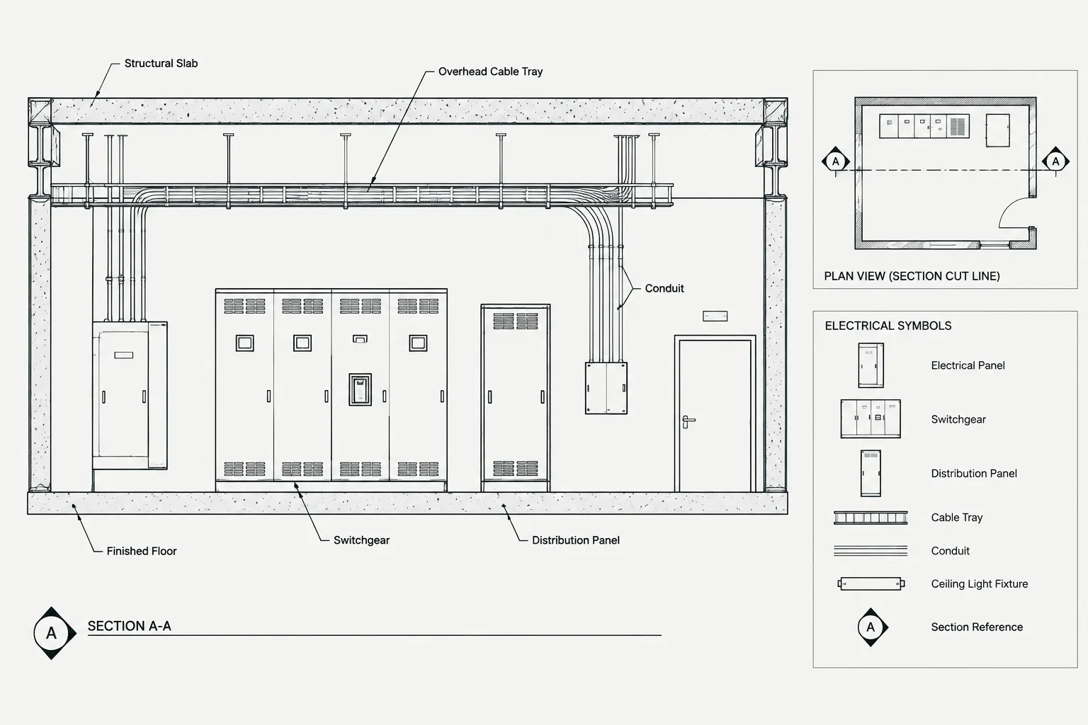
Electrical sections in CAD help drawing teams connect plan-based routing with the vertical conditions that affect equipment, pathways, structure, ceilings, and access. Their usefulness depends not only on accurate geometry, but also on a clearly located cut line, an unmistakable viewing direction, and references that lead readers between related views.
The following guidance focuses on section composition and drawing coordination. It can be used when creating a new section, reviewing a model-derived view, or checking whether an existing section still agrees with the source plan after revisions.
Electrical floor plans are effective for showing horizontal relationships, but they cannot always explain how equipment, raceways, cable trays, ceilings, structures, and access zones relate vertically. Electrical sections in CAD fill that documentation gap by presenting a cut or projected view through a coordinated area.
A useful section is more than a side view of model geometry. It is a deliberately composed drawing that answers a specific coordination question. The drafter must choose the cut location, establish the viewing direction, control the visible depth, identify relevant backgrounds, and connect the section back to its source plan. This guide describes a practical workflow for creating sections that remain readable and traceable across an electrical drawing set.
When an Electrical Section Adds Value
A section should clarify information that is difficult to understand in plan view. Creating one simply because a project has three-dimensional geometry can add maintenance work without improving the documents.
Common reasons to produce an electrical section include:
- Showing vertical separation between conduits, cable trays, busway, structure, and other building systems.
- Coordinating equipment height with ceilings, platforms, doors, louvers, or overhead services.
- Explaining stacked raceway banks, wall penetrations, sleeves, or transitions between routing elevations.
- Showing the relationship between floor-mounted equipment, housekeeping bases, wall-mounted devices, and overhead connections.
- Clarifying electrical room arrangements where a plan alone does not communicate working relationships or routing intent.
- Documenting pathways through shafts, ceiling spaces, trenches, or other constrained areas.
Before drafting, state the section’s purpose in a short internal note. For example, the purpose may be to coordinate an overhead tray crossing or explain how feeders enter a lineup. This helps determine which objects belong in the view and which can be omitted.
Section, Elevation, and Detail: Choosing the Right View
These view types are related, but they do not communicate the same thing.
| View type | Primary purpose | Typical electrical content |
|---|---|---|
| Section | Shows a cut through an area and the relationships beyond the cut plane | Raceway routes, tray elevations, equipment profiles, structure, ceilings, and penetrations |
| Elevation | Shows the face of an object or wall without implying that the assembly has been cut | Panel faces, device arrangements, equipment lineups, wall-mounted controls, and mounting references |
| Detail | Explains a localized condition at a larger graphic scale | Support concepts, sleeve arrangements, connection zones, identification methods, and interface conditions |
A section may contain a detail callout, and an elevation may be derived from the same coordinated model or background. Label each view according to what it actually represents rather than using the terms interchangeably.
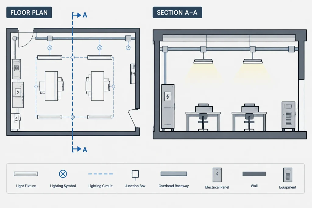
Anatomy of a Section Reference
The plan reference is the reader’s route from the horizontal view to the vertical view. It normally needs to communicate the position of the cut, its viewing direction, and the destination of the resulting section.
Cut line
The cut line identifies where the section is taken. Place it so that it passes through the elements needed to explain the condition. Avoid routing it through unrelated geometry merely to fit the marker into open plan space. If an offset cut is necessary, make each change in the cutting path visually unambiguous.
View direction
Directional arrows or the orientation of the section symbol tell the reader which way the section looks. Verify direction early. Reversing the view later can invert equipment order, move walls to the opposite side, and create avoidable annotation revisions.
Section and sheet reference
The marker should direct the reader to the section identifier and its sheet location according to the project’s established reference system. Avoid manually repeated references when the CAD workflow offers a controlled field, attribute, or sheet-data process. Whatever method is used, the plan marker and section title must agree.
A Practical CAD Drafting Workflow
1. Start from a coordinated source plan
Confirm that the architectural, structural, mechanical, plumbing, and electrical backgrounds used for the section correspond to the same coordination issue. A section generated from an outdated background may appear precise while documenting an obsolete condition.
2. Define the cut and depth of view
Decide what is physically cut and what remains visible beyond the cut plane. Excessive depth can introduce doors, equipment, grids, and services that have no bearing on the electrical condition. Too little depth can hide the context needed to understand routing or access.
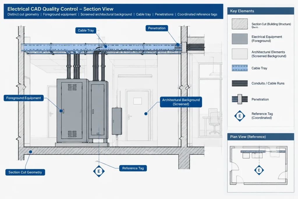
3. Separate cut, profile, and background graphics
Objects intersected by the cut plane should be visually distinguishable from objects seen beyond it. Electrical equipment and pathways must also remain legible against architectural and structural context. Use the project’s layer, lineweight, screening, and plotting conventions rather than assigning arbitrary appearance overrides.
4. Add electrical information selectively
Show the electrical elements necessary to communicate the condition: equipment outlines, tray or raceway paths, connection zones, penetrations, supports when relevant, and identification tags. Do not turn the section into an inventory of every nearby device. Information already documented clearly in a schedule or plan can often be referenced rather than repeated.

5. Establish vertical references
Vertical information should connect to recognizable project datums or named building elements. Depending on the drawing purpose, this may include floor levels, ceiling planes, structural members, equipment bases, or routing elevations. Use consistent terminology, and distinguish confirmed project information from conceptual or coordination-only geometry.
6. Add notes and cross-references
Notes should explain interfaces, scope, or unusual representation—not restate what the graphics already show. Reference related plans, elevations, diagrams, or details when they provide necessary information. Check that every reference resolves to an issued or intentionally included view.
Managing Layers and Reusable Geometry
Sections often combine geometry from several sources, so disciplined layer control is important. Keep electrical section objects separate from imported or referenced backgrounds. Useful categories may distinguish equipment, pathways, hidden or overhead features, annotations, dimensions, reference geometry, and nonplot construction lines. Actual layer names should follow the project’s CAD standard.
Avoid copying uncontrolled background linework into the electrical file merely to make the section appear complete. Copied geometry can become disconnected from later architectural or structural revisions. Where practical, retain traceable references and use electrical overlay geometry only when needed for clarity or issue control.
Reusable CAD blocks can improve consistency for section markers, equipment profiles, tray profiles, and common annotations. However, every reused element must be checked against the current project’s orientation, scale behavior, attribute content, and actual design information. A library profile is a drafting starting point, not proof of equipment size or suitability.
Coordinating Plans and Sections
The floor plan and section should describe the same arrangement from different viewpoints. Review them together rather than checking each sheet independently.
- Compare equipment order and orientation in both views.
- Confirm that pathways enter and leave equipment on the same sides.
- Check that penetrations align with walls, floors, and shafts shown in plan.
- Verify that tags and equipment identifiers match schedules and diagrams.
- Confirm that overhead and below-floor linework uses the drawing set’s established conventions.
- Check whether a plan revision requires the section cut, section graphics, or both to change.
Where a section shows conceptual routing rather than a fully coordinated path, label the intent appropriately. Detailed-looking linework should not imply verified geometry when the route is still subject to coordination.
Common Drafting Problems
Unclear cut location
A marker placed near equipment without clearly crossing it leaves the reader unsure whether the section represents the equipment centerline, face, or surrounding space. Adjust the cut and symbol so the relationship is explicit.
Too much background detail
Dense background geometry can overpower the electrical content. Control visible depth, screen secondary information, and suppress irrelevant objects while retaining enough context to orient the reader.
False precision
Exact-looking offsets or equipment profiles may be interpreted as verified project data. Do not derive dimensions from generic blocks or unverified manufacturer imagery. Mark preliminary or diagrammatic information according to the project’s documentation conventions.
Broken references after sheet changes
Moving a section to another sheet can leave stale plan markers and note references. Include reference validation in the sheet-reorganization and revision workflow.
Duplicate information that drifts apart
Repeating tags, elevations, and notes across plans, sections, and details creates more opportunities for conflict. Establish a primary location for each item of information and use cross-references where repetition adds little value.
Section Quality-Control Checklist
- Does the section answer a defined coordination or documentation question?
- Is the cut line located correctly on the source plan?
- Does the marker show the intended viewing direction?
- Do the section identifier and sheet reference match the section title?
- Are cut objects, objects beyond, and background information visually distinct?
- Are equipment orientation and pathway routing consistent with the plan?
- Are vertical references based on coordinated project information?
- Are electrical tags consistent with schedules, diagrams, and related views?
- Has irrelevant background detail been removed or subdued?
- Are generic CAD blocks and profiles clearly verified or treated as placeholders?
- Do all detail and sheet references resolve correctly?
- Has the plotted output been reviewed at its intended presentation size?
Building Sections as Part of the Drawing System
The strongest electrical sections are not isolated illustrations. They form part of a connected documentation system that includes plans, schedules, elevations, diagrams, details, and equipment data. Their value comes from showing vertical relationships while preserving clear references to the rest of the set.
By defining the purpose of each cut, limiting the depth of view, controlling graphic hierarchy, and validating references during revisions, CAD teams can create sections that resolve coordination questions without adding unnecessary drawing complexity.
A Plan-to-Section Review Sequence
A reliable review starts with the source plan rather than the finished section. Locate the section marker, follow its viewing direction, and identify the objects crossed by the cut. Then compare those objects with the section from the near side of the view toward the background. This sequence helps reveal mirrored arrangements, missing penetrations, reversed equipment order, and pathways that appear to connect differently between views.
Next, review the section as a documentation hierarchy. Cut elements should read first, relevant electrical content should remain prominent, and supporting architectural or structural information should provide context without dominating the view. Finally, validate the section title, destination reference, equipment tags, and related detail callouts as a connected group.
Handling Changes During Coordination
Not every project revision affects a section in the same way. A background change may alter visible context without moving the electrical route, while an equipment relocation may require updates to the plan marker, section geometry, annotations, and cross-references. Treat the section as a dependent view even when it is drafted manually.
- Plan change: Check whether the cut still passes through the intended condition.
- Orientation change: Confirm that the viewing direction and object order remain correct.
- Background change: Review clearances, penetrations, ceilings, and structural relationships shown graphically.
- Sheet change: Revalidate every marker, title, and note that points to the relocated view.
- Block replacement: Confirm orientation, attributes, and graphic behavior instead of assuming the new block is interchangeable.
Preparing the Section for Drawing Handoff
Before issue, review the section in the same plotted context in which it will be read. Layer colors or model-space clarity do not guarantee a readable sheet. Screening, lineweight, hatching, annotations, and referenced backgrounds should work together after plotting.
The handoff should also make the status of the geometry understandable. Verified project information, referenced background content, and conceptual routing should not appear equally authoritative when they have different levels of coordination. Clear notes and consistent graphic conventions help later reviewers understand what must be maintained when the drawing changes.
Frequently Asked Questions
What does a cut line represent on an electrical plan?
A cut line identifies the location or path from which a section is developed. It should cross the equipment, pathway, penetration, or coordinated area that the resulting view is intended to explain.
Why is view direction important in a section marker?
View direction determines which side of the cut the reader looks toward. An incorrect or ambiguous direction can reverse equipment order and make the section conflict with the plan.
When should an electrical elevation be used instead of a section?
Use an elevation when the main purpose is to show the face or arrangement of equipment or wall-mounted devices without representing a physical cut through the surrounding area. Use a section when relationships through and beyond a cut plane are important.
Can a section be generated directly from a coordinated model?
Yes, but generated geometry still requires editorial control. The drafter should manage view depth, visibility, annotations, graphic hierarchy, and references so the output answers the intended coordination question.
Should every nearby electrical object appear in the section?
No. Include objects that establish the condition, support coordination, or help the reader orient the view. Unrelated devices and distant background geometry can reduce clarity.
How should generic CAD blocks be treated in electrical sections?
Use them as drafting resources rather than verified project data. Their orientation, attributes, appearance, and represented geometry should be checked against current project information before issue.
What should be checked after a section moves to another sheet?
Review the source-plan marker, section title, sheet destination, note references, and related detail callouts. Any manually entered reference may remain stale after the move.



Leave a Reply
You must be logged in to post a comment.