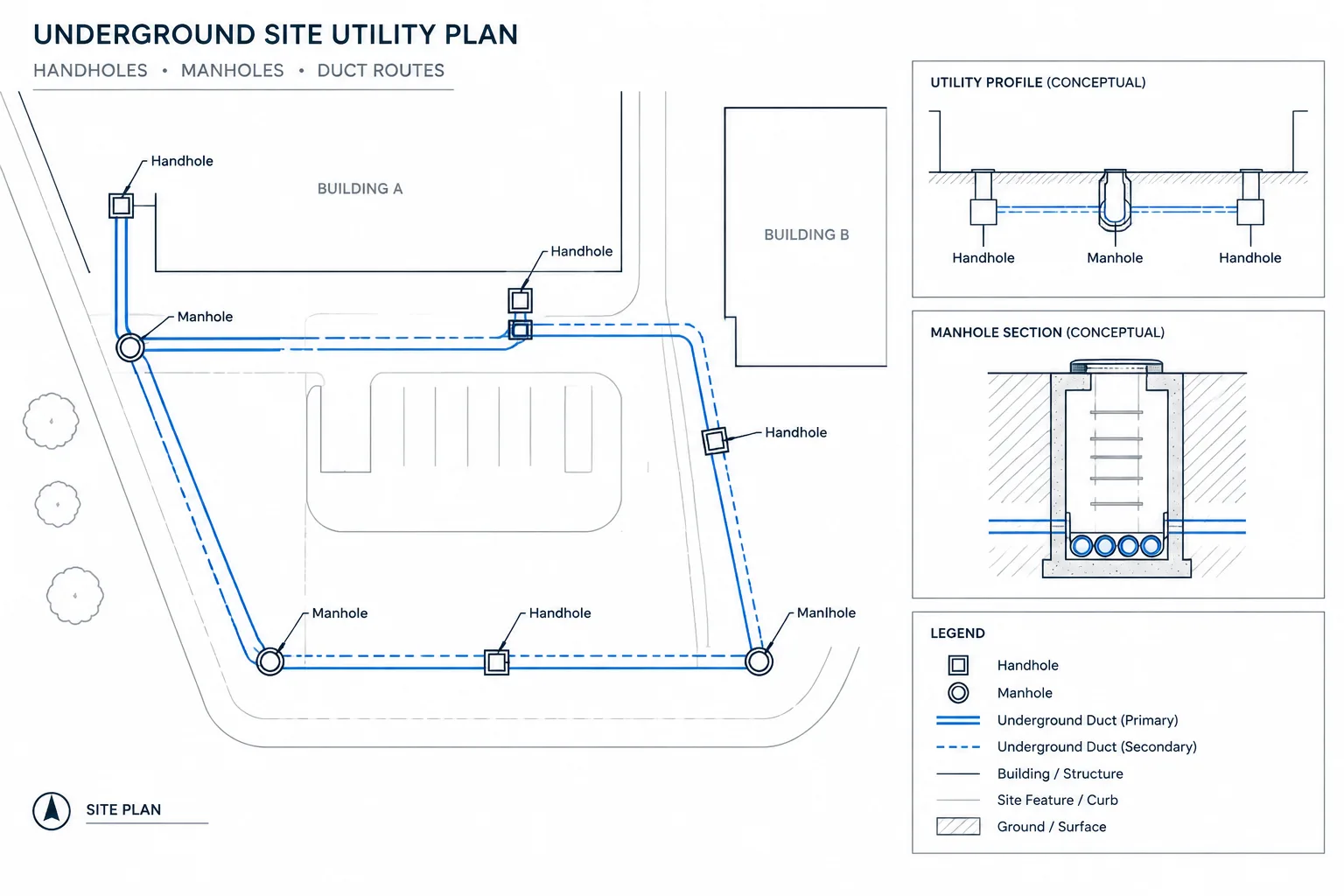
Electrical manhole and handhole drawings in CAD must explain more than enclosure locations. They should show how underground pathways connect, where related information is documented, and which conditions still require coordination. The following reference outlines a drawing-centered approach to plans, profiles, sections, schedules, cable records, and route identification.
Use the guidance as a documentation framework rather than an enclosure design template. Project professionals must verify the physical configuration, structural requirements, utility criteria, access provisions, and installation details.
Electrical manholes and handholes are more than rectangular symbols placed along an underground route. Each enclosure is a coordination point where raceways enter, cables change direction, pulling segments begin or end, and civil conditions affect the electrical layout. A useful CAD drawing must connect the site plan to the underground pathway documentation, enclosure details, cable information, and equipment served.
This guide focuses on drafting and documentation rather than construction methods. Actual enclosure selection, structural design, access provisions, cable pulling criteria, drainage, grounding, and installation requirements must be verified by the responsible project professionals.
Manhole and handhole documentation at a glance
The terms manhole and handhole generally distinguish different types of accessible underground enclosures, but naming conventions vary among owners, utilities, and project teams. Do not rely on the generic symbol alone to communicate size, access, structural characteristics, or intended use. Assign each enclosure a unique identifier and connect it to verified project information.
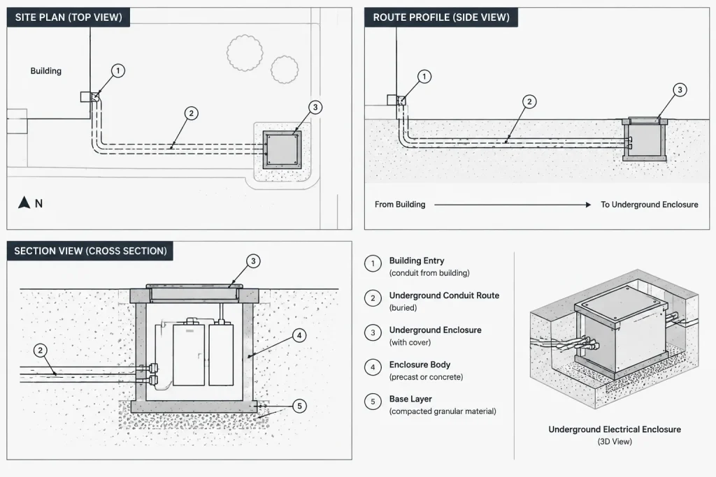
An underground electrical documentation package may show an enclosure in several coordinated views:
- Site or utility plan: Establishes location, route direction, nearby features, and the equipment or building served.
- Enlarged plan: Clarifies duct entrances, route transitions, internal routing intent, and congested surroundings.
- Profile: Shows the vertical relationship among the enclosure, raceways, grades, and crossing utilities.
- Section or detail: Communicates enclosure configuration, openings, access, and interfaces that cannot be understood in plan view.
- Schedule: Collects identifiers, descriptions, connected routes, status, and applicable detail references.
- Cable or feeder documentation: Identifies the circuits or cables passing through, terminating in, or branching from the enclosure.
Start with a route-centered CAD model
Draft the underground pathway as a connected system rather than as isolated enclosure blocks. Begin with the verified project base, including buildings, property information, roads, paving, grading references, landscape features, and known utilities. Keep electrical route geometry separate from the background so it can be reviewed, revised, and plotted independently.
Place preliminary enclosure symbols where the route changes direction, branches, approaches equipment, or requires an identified access point. These locations are coordination decisions, not merely drafting conveniences. Label preliminary information accordingly until route feasibility and enclosure characteristics are confirmed.
Use a consistent insertion point for each enclosure block. A logical reference point, such as the geometric center or a defined corner, makes coordinate comparison easier. If coordinates or station references are required, derive them from the shared project base rather than manually typing disconnected values into notes.
Separate location graphics from descriptive data
The plan symbol should remain readable at the plotted scale. Detailed data can be stored in block attributes, schedules, callouts, or linked project records. Useful fields may include:
- Unique enclosure identifier
- General enclosure category
- Existing, new, future, or removal status
- Connected route identifiers
- Associated feeder or cable references
- Plan, profile, section, and detail references
- Responsibility or utility interface notes
- Verification status for unresolved information
Avoid embedding unverified dimensions or product descriptions in a reusable block. The block should support documentation without implying that one enclosure configuration is universally suitable.
Coordinate route identifiers and duct entrances
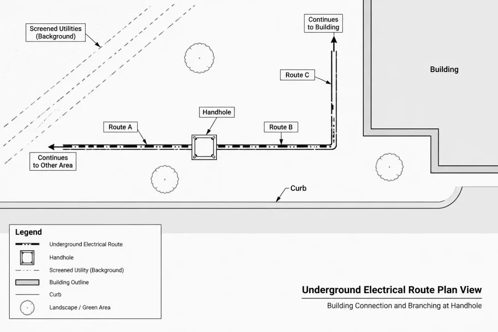
Every pathway entering or leaving an enclosure should be traceable. Assign route identifiers that remain consistent across the site plan, profile, sections, duct bank documentation, and schedules. A reader should be able to follow a route from its origin, through intermediate enclosures, to its destination without guessing which line continues.
At simple locations, route tags adjacent to the enclosure may be sufficient. At congested intersections, use an enlarged plan or a dedicated entry diagram. Arrange route graphics so their direction of approach is visually clear. Do not place multiple line ends against an enclosure symbol without indicating which route each line represents.
When an entrance face matters, identify it using a project-consistent directional method or a referenced section. The labels used on plans must agree with those used in enclosure views. Rotated viewports and changing sheet orientation can make informal terms such as left and right unreliable.
Use the right drawing view for each question
| Documentation question | Best drawing location | Typical information |
|---|---|---|
| Where is the enclosure? | Site or utility plan | Identifier, route, nearby features, destination, and reference callouts |
| How do pathways approach it? | Enlarged plan | Route IDs, entrance direction, bends, branches, and spatial conflicts |
| How does it relate to grade and crossings? | Profile | Vertical route relationships, surface references, and crossing coordination |
| What is the enclosure configuration? | Section or detail | Openings, access orientation, pathway interfaces, and referenced components |
| Which cables pass through it? | Cable schedule or route diagram | From-to data, cable IDs, route references, and termination or pass-through status |
| What remains unresolved? | Notes, issue log, or coordination markup | Pending utility data, field verification, civil input, or equipment information |
Do not overload one drawing with every category of information. A clean site plan supported by profiles and details is usually easier to review than a plan filled with enclosure dimensions, cable lists, elevations, and construction notes.
Document cable routing without drawing false precision
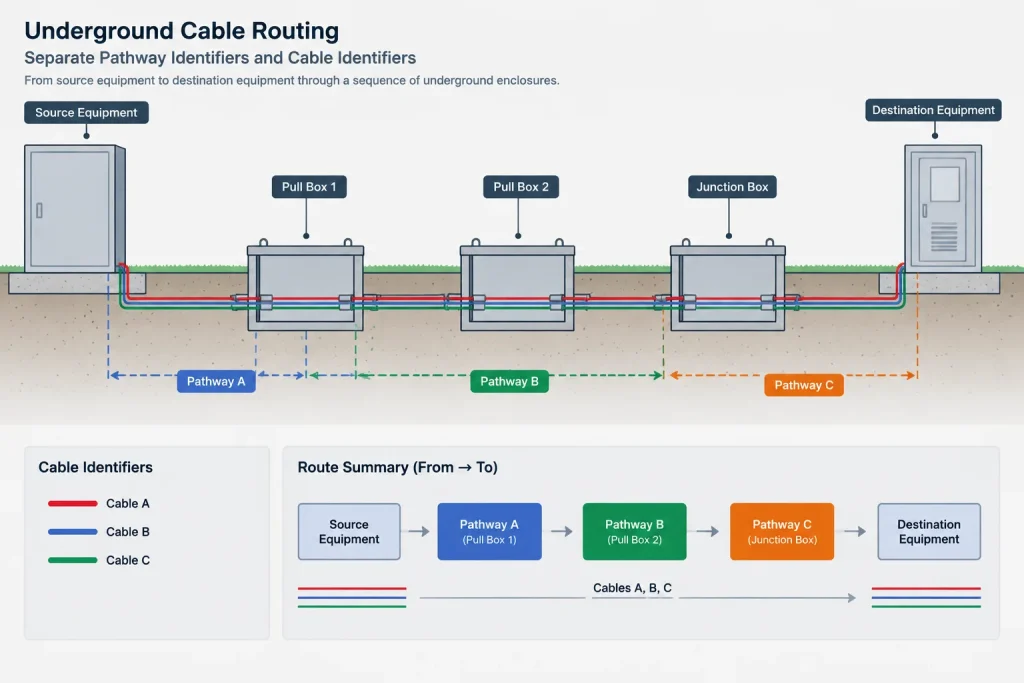
A cable route through an enclosure may need to communicate continuity, branching, splicing intent, or termination. The necessary level of detail depends on the project. On a site plan, cable or feeder tags can reference a schedule. A route diagram can then show the sequence of enclosures and endpoints without reproducing the physical geography.
If internal cable arrangement is shown, distinguish diagrammatic routing from verified physical placement. Smooth arcs can communicate continuity, but they should not imply a confirmed bend geometry or cable length unless that information has been engineered and coordinated. Likewise, avoid depicting supports, splice locations, or pulling hardware as generic assumptions.
Keep pathway identity separate from cable identity. One route may contain multiple cables, and one cable may pass through several pathway segments. Separate identifiers reduce ambiguity when either the pathway or cable assignment changes.
Coordinate civil, structural, and utility information
Underground enclosure drawings often sit at the boundary between disciplines. The electrical plan may establish functional routing, while civil drawings provide grades and paving information. Structural documentation may define enclosure construction, and a utility may control portions of the route or connection.
Use external references or other controlled background methods so changes remain visible. Avoid tracing civil features onto electrical layers unless the copied geometry has a specific documentation purpose. Traced information can become outdated while still appearing authoritative.
Review each enclosure against surrounding conditions such as roads, curbs, drainage features, building foundations, landscape areas, retaining elements, and other utilities. Show only verified relationships, and flag unresolved conflicts for coordination rather than resolving them graphically without design input.
Build a practical enclosure schedule
An enclosure schedule provides a compact index for cross-checking the drawings. Its columns should reflect available project data rather than a generic template filled with assumptions. Possible fields include identifier, location description, status, connected route IDs, enclosure reference, cable reference, detail number, and remarks.
Use the schedule as an index, not as a substitute for drawings. A location description such as near a building entrance may help reviewers, but it does not replace plan geometry. Similarly, a type designation is useful only if that type is clearly defined elsewhere in the project documents.
CAD layer and block strategy
Organize enclosure documentation so users can isolate symbols, routes, text, dimensions, and backgrounds. A project may also separate new, existing, future, and removal work through layers or another controlled graphic method. Whatever system is selected, status must remain understandable in both color and monochrome output.
Create blocks with simple plan geometry and stable attribute fields. If several enclosure categories share the same basic symbol, a type attribute may be more manageable than numerous nearly identical blocks. If their plotted shapes communicate different meanings, separate blocks may be clearer. Test attribute visibility, rotation, mirroring, and plotting before adding the blocks to a shared library.
Quality-control review before issue
- Confirm that every enclosure identifier is unique and appears consistently in plans, profiles, details, and schedules.
- Trace every route through each enclosure and verify that continuation labels agree.
- Check that cable and feeder references match the current schedules and diagrams.
- Compare enclosure locations with the latest civil and utility backgrounds.
- Verify that entrance directions agree among plans, sections, and details.
- Look for duplicated symbols, abandoned route lines, hidden notes, and outdated callouts.
- Confirm that existing, new, future, and removal statuses remain distinguishable when plotted.
- Identify unverified dimensions, elevations, ownership boundaries, and utility information rather than presenting them as final.
- Review crowded areas at the intended sheet scale, not only while zoomed in within model space.
A coordinated drawing is more useful than a detailed symbol
The value of an electrical manhole or handhole drawing comes from connected information. A simple symbol can be effective when its identifier leads to the correct route, profile, cable record, schedule entry, and detail. Conversely, an elaborate block cannot compensate for inconsistent route tags or missing cross-references.
Treat underground enclosures as nodes in a documented network. Keep route geometry traceable, use each drawing view for a defined purpose, and separate verified design information from placeholders. This approach produces CAD files that are easier to review, revise, and coordinate throughout the project.
How to read the completed drawing package
A reviewer should be able to understand the underground system at three connected levels. The site plan establishes geographic location, the route graphics explain network continuity, and the supporting views provide information that cannot be communicated clearly at plan scale. Cross-references are what bind these levels together.
Begin a review at an enclosure identifier and follow every connected route in both directions. Confirm that each route leads to a recognizable origin, destination, branch, or continuation reference. Then compare the enclosure with its profile, section, schedule entry, and cable documentation. A break in that chain usually indicates missing information even when the individual drawings appear complete.
Manage revisions as coordinated data changes
Moving an enclosure can affect route geometry, profiles, crossing coordination, callouts, and location descriptions. Changing a route identifier can affect schedules, diagrams, and cable records. Treat these edits as coordinated changes rather than isolated drafting corrections.
Revision review should also distinguish a graphic change from a design change. Adjusting text placement for legibility does not alter the documented system, while relocating an enclosure or redirecting a pathway may require renewed multidisciplinary review. Clear revision notes and controlled backgrounds help reviewers identify that difference.
Keep assumptions visible
Preliminary information should not look indistinguishable from verified project data. Use the project’s approved status graphics, notes, attributes, or issue-tracking method to identify pending utility input, field verification, civil coordination, or equipment information. This allows the CAD file to remain useful during development without presenting placeholders as final decisions.
Frequently asked questions
What should an electrical manhole or handhole symbol show?
The plan symbol should provide a clear location and unique identifier at the intended plotting scale. Enclosure characteristics, route connections, status, and supporting references can be carried by attributes, callouts, schedules, or related details rather than crowded into the symbol.
When is an enlarged plan needed?
An enlarged plan is useful when several pathways approach an enclosure, entrance directions are unclear, nearby utilities create congestion, or the site plan cannot show route relationships legibly. It should clarify verified spatial relationships without implying unconfirmed internal construction.
Why are both route IDs and cable IDs needed?
A pathway and the cables using it are different documentation objects. A route may carry several cables, while a cable may continue through several pathway segments and enclosures. Separate identifiers allow either record to change without confusing physical routing with circuit or feeder continuity.
Should internal cable routing be drawn inside the enclosure?
Show internal routing only when it serves a defined documentation purpose and its meaning is clearly stated. Diagrammatic lines may communicate continuity or branching, but they should not imply verified placement, bend geometry, support locations, or cable length.
How should unresolved enclosure information be documented?
Mark it through the project’s established notes, status attributes, coordination comments, or issue log. Identify the information requiring confirmation and the related discipline or project party without graphically inventing a solution.












Leave a Reply
You must be logged in to post a comment.