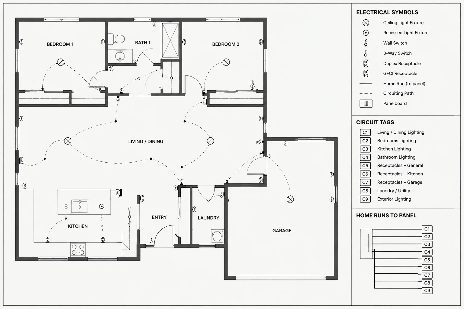
Electrical circuit tags in CAD are small annotations with a large coordination role. They help readers trace a device or connected group from the plan to its documented source, schedule entry, and distribution diagram. The following guidance explains how to structure, place, review, and revise these tags without treating them as isolated pieces of text.
Electrical circuit tags connect plan symbols to the rest of the electrical drawing set. A receptacle, lighting fixture, equipment connection, or junction box may be clearly drawn, but without a coordinated circuit identifier, the reader may not know which panel, distribution point, or schedule entry applies.
Good circuit tagging is not simply a matter of placing text beside devices. It is a documentation system that must remain consistent across plans, panel schedules, single-line diagrams, risers, details, and revisions. The drafting workflow should make tags readable while also making discrepancies easy to find.
What an Electrical Circuit Tag Communicates
A circuit tag usually identifies the source serving a device or group of devices. Depending on the project and drawing type, it may contain a panel designation, circuit reference, system designation, or another source identifier established by the project documentation.
The exact tag format should follow the project’s drafting standard and electrical design workflow. A tag may be presented as plain text, an attributed block, a keynote-like symbol, or a label attached to circuiting linework. The important point is that the same information must mean the same thing throughout the drawing set.
Common information associated with circuit tags includes:
- The serving panel or distribution equipment designation
- The applicable circuit reference or schedule position
- A normal, backup, controlled, or other documented power classification
- A phase or pole relationship when that information belongs on the drawing
- A shared circuit reference for a connected device group
- A note or cross-reference when circuit information is defined elsewhere
A circuit tag should not be treated as a substitute for design calculations, conductor documentation, protective-device information, or the panel schedule. Its role is to provide a reliable link between drawing elements.
Choose a Consistent Tag Structure
Before circuiting a plan, define how identifiers will be assembled and displayed. A stable structure reduces interpretation problems and helps CAD users search, filter, and compare information.
| Tag component | Purpose | Coordination question |
|---|---|---|
| Source designation | Identifies the serving panel or equipment | Does it exactly match the designation used on schedules and diagrams? |
| Circuit reference | Links the plan device to a schedule entry | Is it current, legible, and assigned to the correct source? |
| System or status marker | Distinguishes documented power categories | Is the marker explained by the legend or drawing notes? |
| Grouping convention | Shows which devices share an identifier | Can the reader determine the intended group without guessing? |
| Cross-reference | Directs the reader to another drawing or schedule | Does the referenced location exist in the issued set? |
Avoid casual variations such as changing punctuation, adding spaces, abbreviating one panel differently on another sheet, or reversing the order of tag components. These differences may look minor but can interfere with manual review and automated data extraction.
Decide Whether Tags Belong to Devices or Circuit Paths
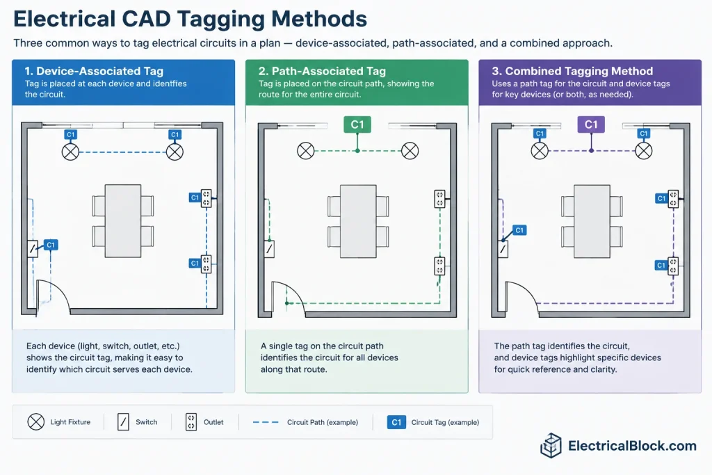
Electrical plans commonly associate circuit identifiers with device symbols, circuiting linework, or both. The best method depends on the type of plan and the established drawing convention.
Device-associated tags
A tag placed beside a device is direct and remains understandable when circuiting arcs are limited or omitted. This approach can work well for equipment connections and isolated devices. It may become visually crowded when many symbols occur in a small area.
Path-associated tags
A tag attached to a circuiting polyline or home-run graphic can identify a connected group without repeating the same text beside every symbol. However, the path must clearly show which devices belong to the group. Ambiguous intersections, gaps, or overlapping linework can weaken the association.
Combined methods
Some drawing sets use path tags for repeated branch devices and individual tags for dedicated or separately documented loads. If methods are combined, define the distinction in the legend or drawing notes rather than expecting readers to infer it.
Build Circuit Tags as Controlled CAD Objects
Plain text can be adequate for a small drawing, but a reusable attributed block often provides better consistency. The block can control text alignment, label order, masking, and insertion behavior while storing each information field separately.
Useful attribute fields may include:
- Panel or source designation
- Circuit reference
- System classification
- Connected equipment identifier
- Review or coordination status stored as non-plot data
Keep visible content separate from internal coordination data. A reviewer should not have to interpret hidden fields to understand the published drawing, and temporary status information should not accidentally appear in a plotted issue.
Use a deliberate insertion point. For example, a tag intended to sit at the end of a home-run line should attach predictably to that endpoint. A device label should maintain a stable offset from the symbol. Consistent insertion behavior makes global repositioning and cleanup easier.

Coordinate Tags with Panel Schedules
The plan and panel schedule should be reviewed as two views of the same documented assignment. A circuit appearing on a plan should point to a valid schedule location, while schedule descriptions should correspond to identifiable loads or areas in the drawings.
A practical review can proceed in both directions:
- Start from each plan tag and confirm that its source exists.
- Locate the corresponding schedule entry and compare the load description.
- Check whether the room, equipment, or device group shown on the plan agrees with that description.
- Review schedule entries that appear assigned but cannot be located on any plan or diagram.
- Identify plan devices that have missing, duplicated, provisional, or obsolete tags.
Do not assume that matching text proves correct coordination. A copied tag can be syntactically valid but attached to the wrong device. The review must consider the actual plan location and intended load.
Coordinate Source Names with Single-Line and Riser Diagrams
Panel and equipment designations used in circuit tags should match the identifiers shown on distribution diagrams. If a panel is renamed, moved under a different source, or divided into separate sections, every dependent reference should be reviewed.
Diagram coordination is especially important when similar equipment names exist in different buildings, floors, tenant areas, or power systems. The plan tag needs enough context to be unambiguous within the drawing package, but it should not become so long that it overwhelms the plan.
Where a shortened plan label is necessary, document the abbreviation and use it consistently. Avoid creating an informal alias that appears only on one sheet.
Manage Tags in Crowded Plan Areas
Circuit tags compete for space with device symbols, room names, dimensions, keynotes, and circuiting graphics. Readability should take priority over keeping every tag immediately adjacent to its object.
Useful drafting techniques include:

- Aligning nearby tags into orderly rows where associations remain clear
- Using short leaders when displacement is necessary
- Applying background masks carefully so essential architectural or electrical information is not hidden
- Breaking dense areas into enlarged views rather than compressing annotations
- Keeping tags clear of walls, equipment outlines, and other text
- Checking final plotted output instead of judging readability only in model space
Leader lines should terminate clearly and should not resemble conductors, circuiting arcs, or control lines. Layer, line type, and graphic style can help distinguish annotation leaders from electrical connectivity.
Handle Unassigned and Provisional Circuits Deliberately
During design development, some devices may not yet have final circuit assignments. Avoid filling these locations with realistic-looking identifiers merely to make the plan appear complete. Use a controlled placeholder or documented status convention that is visibly different from finalized circuit information.
Before issue, search the drawing database for placeholders, empty attributes, temporary panel names, and unresolved notes. A graphical review alone may miss tags hidden behind other objects or outside active viewports.
Revision Workflow for Circuit Changes
Circuit revisions often affect more than one label. A changed assignment may require updates to the plan tag, panel schedule, load summary, diagram, equipment note, or related detail.
When revising a circuit:
- Identify every occurrence of the source and circuit reference.
- Confirm that copied plans, enlarged views, and dependent details are included.
- Update the schedule and diagram references as part of the same change.
- Check whether the previous assignment is now unused or reassigned.
- Compare the revised sheet against the prior issue to catch unintended changes.
- Remove revision graphics only according to the project’s issue-control process.
Find-and-replace tools can help with renamed equipment, but they should not replace contextual review. The same text may occur in notes, unrelated areas, or archived objects where an automatic replacement would be incorrect.
Final Circuit Tag Quality-Control Checklist
- Every required device or connected group has an understandable source reference.
- Panel and equipment names match schedules and distribution diagrams.
- Tag formatting is consistent across sheets and plan types.
- Text remains readable at the published sheet scale.
- Leaders and circuit paths do not create false connections.
- Provisional identifiers and empty attributes have been resolved.
- Copied, mirrored, and repeated areas have been individually verified.
- Enlarged plans agree with their parent plans.
- Schedule descriptions correspond to recognizable plan loads or locations.
- Obsolete tags, duplicate text, and objects outside viewports have been checked.
Reliable electrical circuit tags make a drawing set easier to navigate and easier to review. By treating tags as coordinated data rather than isolated text, CAD teams can reduce mismatches between plans, schedules, and diagrams while producing documents that remain clear through design changes and final issue preparation.
Separate Graphic Consistency from Data Consistency
A circuit tag can look correct while containing outdated or incorrectly associated information. Graphic review checks text height, alignment, masking, leaders, layers, and plotted clarity. Data review checks whether the source designation and circuit reference agree with schedules, diagrams, and the actual device being served. Both reviews are necessary because a visually uniform set can still contain coordination errors.
Check Circuit Tags During File Exchange
When drawings move between CAD platforms, consultant files, or external references, confirm that attributed tags remain usable. Exploded blocks, substituted fonts, detached leaders, missing reference files, and converted text can change how the information appears or prevent reliable searching.
A practical exchange review should verify that:
- Visible tag fields remain legible and correctly ordered.
- Attributes have not become unrelated text objects.
- Leaders still point to the intended devices or circuit paths.
- Layer visibility does not suppress required identifiers.
- Exported sheets show the same circuit information as the working file.
Review Relationships, Not Just Individual Labels
The most useful quality-control question is not simply whether a tag exists. Reviewers should determine whether the complete relationship is valid: the tag identifies the intended device, the named source exists, the schedule includes the assignment, and the applicable diagram uses the same equipment designation.
This relationship-based review also helps distinguish drafting defects from design questions. Missing text, overlapping labels, and inconsistent formatting are drawing issues. Conflicting assignments or unclear source relationships should be returned to the responsible design team rather than resolved through unsupported drafting assumptions.
Prepare Tags for Long-Term Drawing Maintenance
Consistent blocks, attributes, layers, and naming conventions make later revisions easier. Before archiving or handing off a drawing set, remove abandoned tag objects, retain understandable field names, and document any project-specific abbreviations. A maintainable tag system allows future users to locate and compare circuit references without reconstructing the original drafting logic.
Frequently Asked Questions
What is the purpose of an electrical circuit tag?
An electrical circuit tag links a plan symbol or connected device group to its documented source and circuit assignment. It supports navigation between plans, schedules, and distribution diagrams but does not replace the information contained in those documents.
Should a circuit tag be attached to a device or to circuiting linework?
Either method may be used when it follows the project convention and remains unambiguous. Device-associated tags provide a direct local reference, while path-associated tags can reduce repeated text for connected groups. A drawing legend or note should explain any combined approach.
Why use attributed blocks instead of plain text?
Attributed blocks can standardize field order, alignment, insertion behavior, and searchable information. Plain text may still be appropriate in some workflows, but it is more vulnerable to inconsistent formatting and disconnected edits.
How should unassigned circuits be shown?
Use a controlled provisional convention that is visibly different from finalized information. Do not insert realistic-looking assignments merely to fill an incomplete tag, and search for unresolved placeholders before issue.
What should be checked after a panel designation changes?
Review every dependent plan tag, schedule, diagram, enlarged view, note, and detail. Automated replacement may assist with locating references, but each occurrence still requires contextual verification.
Can matching tag text confirm that coordination is correct?
No. Matching text only confirms that the labels are similar. The reviewer must also verify that the tag is associated with the intended device, location, load description, and source.











Leave a Reply
You must be logged in to post a comment.