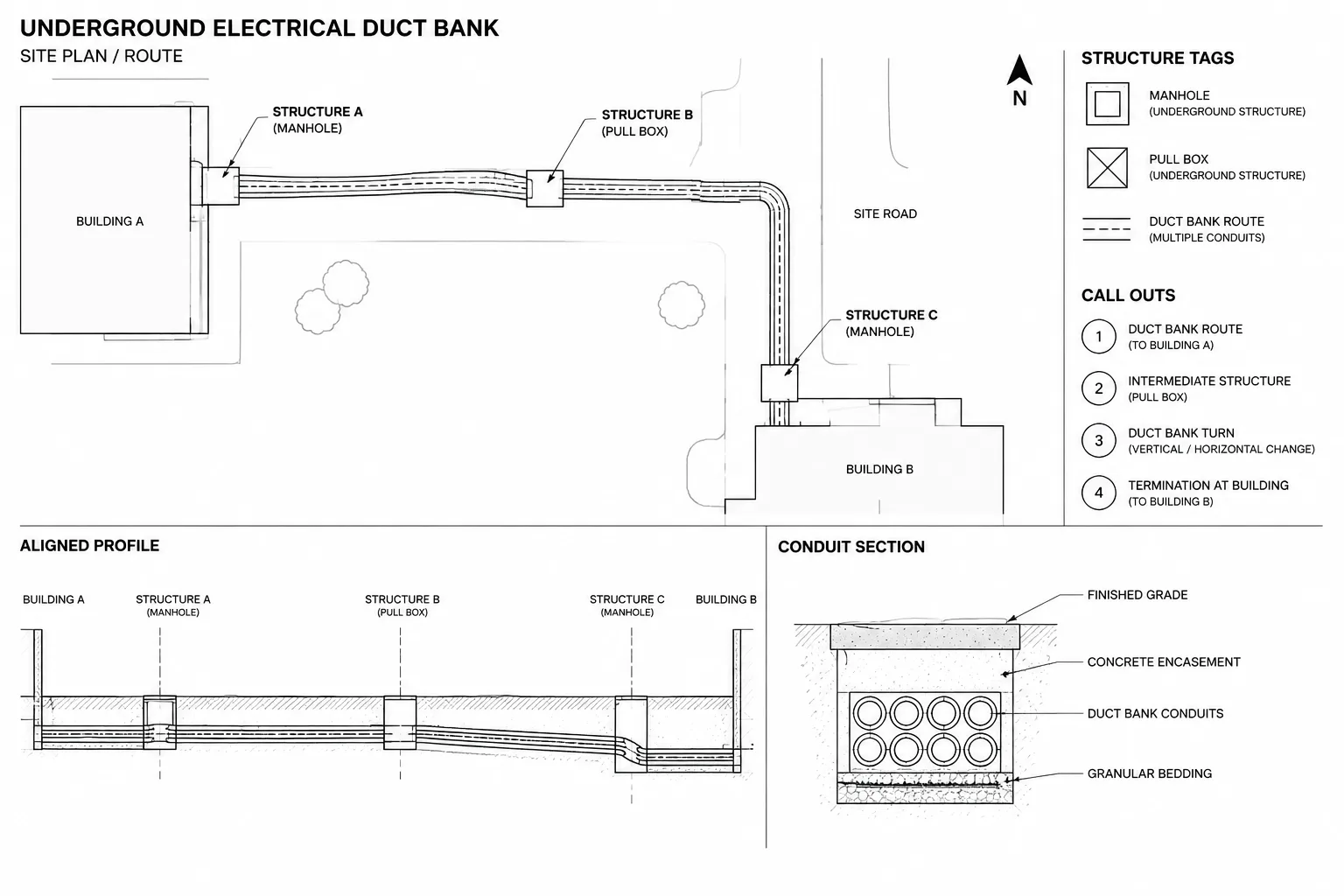
Electrical duct bank drawings in CAD must coordinate horizontal routing, vertical position, conduit arrangement, and pathway identity across several related views. Their usefulness depends less on any single detail than on whether a reviewer can trace the same route consistently through plans, profiles, sections, schedules, and continuation references.
The following reference explains how to organize that information without presenting uncertain backgrounds or typical details as verified project conditions. It is intended for drafting, design coordination, drawing review, and educational use. Final geometry, notes, dimensions, and installation requirements should always be checked against approved project information and the responsible design documents.
Electrical duct bank drawings communicate more than an underground route. A useful drawing set must explain where the route travels, how its elevation changes, which conduits belong in each segment, and how the installation interfaces with buildings, utility structures, roads, and other buried systems.
This information is rarely clear in a single view. Plan drawings establish horizontal location, profiles explain vertical relationships, and sections show conduit arrangement. Schedules, notes, and identifiers connect those views into one coordinated documentation system.
The drafting goal is not to model every construction condition. It is to provide a traceable route description that can be checked against the project design, civil background, utility information, equipment connections, and applicable project requirements.
What an Electrical Duct Bank Drawing Set Should Communicate
A duct bank package should let a reviewer follow a route from its origin to its destination without guessing which plan segment, section, or structure comes next. Depending on project scope, the documentation may include:
- A site plan showing the horizontal route and endpoints
- Enlarged plans at congested areas, turns, and building entries
- Profiles showing route elevation and utility crossings
- Typical and project-specific duct bank sections
- Manhole, handhole, vault, or pull-box references
- Conduit or duct identifiers tied to schedules and diagrams
- Continuation references where the route crosses sheet boundaries
- Notes identifying scope limits, assumptions, and required verification
The drawings should distinguish design intent from information supplied by surveyors, civil consultants, utilities, vendors, or existing-condition records. A line copied from a background file should not appear more certain than its source supports.
Plan View: Establishing the Horizontal Route
The plan view is the primary route map. It should show the duct bank in relation to recognizable project geometry such as building outlines, property features, curbs, roads, equipment pads, and underground structures.
Use a Controlled Route Centerline
A continuous polyline or other controlled path object can provide a stable basis for the route. It is easier to edit and review than a collection of unrelated line segments. Where separate duct banks share part of a corridor, avoid stacking indistinguishable lines directly on top of one another. Use route identifiers, offsets, or a clearly explained composite notation.
Route linework should remain visually distinct from utilities, boundaries, and architectural backgrounds. The duct bank does not need to dominate the sheet, but its path and transitions must remain legible when plotted.

Identify Meaningful Route Changes
Annotate locations where the documented condition changes. Examples include:
- A change in conduit quantity or arrangement
- A transition between duct bank construction types
- An entry into a building or electrical structure
- A branch toward a separate destination
- A significant horizontal or vertical direction change
- A segment that continues on another sheet
Do not place labels at arbitrary intervals simply to fill the drawing. Each callout should help the reader understand a transition, destination, section, or route identity.
Coordinate Endpoints
Every route should terminate at a clearly documented point. The endpoint might be equipment, a building entry, a utility-defined connection point, or an underground structure. Coordinate the endpoint name with the equipment plan, one-line diagram, site utility plan, and relevant schedule.
A generic line ending near equipment is not the same as a defined connection. If the exact entry point depends on approved equipment information or field coordination, state that limitation rather than implying false precision.
Profile View: Explaining Vertical Relationships
A plan can show that two systems cross, but it usually cannot show which one passes above the other. A profile provides the vertical information needed to understand grade changes, structure interfaces, and underground conflicts.
A useful profile may show:
- Existing and proposed grade references
- Duct bank top, bottom, centerline, or another consistently defined elevation reference
- Building foundations and underground electrical structures
- Crossing utilities identified by system and source
- Horizontal route references that connect the profile to the plan
- Vertical bends or transitions
- Limits where information is approximate or requires verification
Clearly state which part of the duct bank an elevation refers to. Mixing centerline, top, and bottom elevations without labels creates avoidable ambiguity.
Align Plans and Profiles
Profiles are easier to review when route stations, structure IDs, segment labels, or other common references correspond with the plan. A reader should be able to locate a crossing in profile and then find the same location on the site plan.
If a profile is diagrammatic or has different horizontal and vertical presentation scales, label that condition clearly. Avoid letting a visually exaggerated slope appear to represent a construction angle.

Sections: Showing Conduit Arrangement
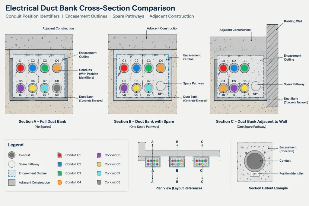
Sections describe the physical organization that a route centerline cannot communicate. They may show conduit grouping, spare positions, separation between systems, encasement limits, warning or identification elements, and relationships to adjacent construction.
Use a typical section only where the same configuration genuinely applies. When conduit arrangement, encasement, surrounding construction, or routing conditions change, create a separate section or clearly document the variation.
| Section element | Drafting purpose | Coordination question |
|---|---|---|
| Section identifier | Links the section to plan segments | Is every applicable route segment referenced? |
| Conduit positions | Shows the intended grouping and organization | Does the arrangement agree with the conduit schedule? |
| Conduit labels | Preserves circuit or system identity | Can each pathway be traced to its endpoints? |
| Encasement outline | Defines the represented duct bank assembly | Is the construction type confirmed by project documents? |
| Adjacent features | Explains nearby foundations, utilities, or paving | Does the section match the coordinated background? |
| Notes and dimensions | Documents project-specific requirements | Have values been obtained from verified design sources? |
A section copied from a library should be treated as editable reference content, not automatically accepted project information. Confirm conduit count, configuration, construction, dimensions, and notes before using it.
Conduit and Duct Identification
A consistent identification system connects the physical route to electrical diagrams and schedules. An identifier can represent an individual conduit, a grouped pathway, a route segment, or an entire duct bank. The drawing legend should explain which level the tag represents.
A practical tagging structure should support:
- Origin and destination tracing
- Recognition of different systems or services
- Identification of spare or future pathways where applicable
- Coordination with conduit and cable schedules
- Revision without unnecessary renumbering
Avoid using color as the only differentiator. Colors may change during plotting, PDF conversion, or grayscale printing. Pair color with line type, text, route ID, or another persistent graphic convention.
CAD Layers and Object Organization
Separate layers can make duct bank drawings easier to review and revise. The exact naming system should follow the project CAD standard, but useful object categories may include route centerlines, duct bank outlines, underground structures, conduit labels, profile geometry, section graphics, dimensions, notes, and reference backgrounds.
Keep source backgrounds separate from electrical design linework. Civil utilities, survey features, and architectural foundations should remain identifiable by source so that updates can be incorporated without manually rebuilding the electrical route.
Reusable structures and section graphics can be blocks, but project-specific information should not become trapped in inaccessible nested geometry. Attributes may help manage structure IDs, route tags, or section names when they are applied consistently and checked during issue review.
Managing Crossings and Uncertain Existing Conditions
Underground information often comes from records with different confidence levels. The drawing should not silently convert an approximate utility location into an exact CAD coordinate. Use notes, line conventions, or source references to distinguish surveyed information from record information and conceptual routing.
At important crossings, coordinate the plan and profile together. Confirm that:
- The crossing appears in both views where required
- The same utility or feature name is used in each view
- The relative above-and-below relationship is consistent
- Elevation references use the same datum
- Any required field verification is documented
Clash detection or overlay review can identify apparent conflicts, but it cannot improve the reliability of inaccurate source data. Record the source and status of the information being compared.
Drawing Review Checklist
Before issuing electrical duct bank drawings, perform a route-based review rather than checking each sheet in isolation:
- Trace every duct bank from origin to destination.
- Confirm that route and structure identifiers are unique and consistent.
- Match plan section callouts to the correct section titles.
- Compare conduit arrangements with schedules and one-line diagrams.
- Check sheet-to-sheet continuation references in both directions.
- Verify that plan, profile, and section views describe the same route condition.
- Review crossings against the latest coordinated backgrounds.
- Confirm that elevation references and source datums are identified.
- Remove abandoned geometry, duplicate tags, and superseded callouts.
- Plot the sheets and check readability without relying on layer colors.
Build a Traceable Documentation System
Effective electrical duct bank drawings in CAD function as a connected set of views rather than isolated details. The plan establishes location, the profile explains depth and crossings, the section defines arrangement, and the schedules preserve pathway identity.
CAD blocks and typical details can accelerate production, but they must be verified against the actual project design, equipment interfaces, utility requirements, and coordinated site information. Clear identifiers and reliable cross-references are what turn reusable graphics into useful construction documentation.
Using the Route as the Drawing Data Backbone
A practical CAD workflow treats the route identifier as the common reference connecting every view. The identifier shown beside a plan centerline should lead the reviewer to the applicable profile, section, structure reference, and schedule entry without requiring interpretation based only on line position.
This approach is especially useful during revisions. When an endpoint, crossing, conduit arrangement, or construction condition changes, the route identity provides a clear list of related drawing objects to review. It also helps prevent a revised plan from being issued with an outdated profile or section.
Separate Geometry from Descriptive Data
Route geometry and route data serve different purposes. Geometry shows where the duct bank is represented, while labels, attributes, schedules, and notes explain what the route means. Keeping those functions organized makes it easier to update the path without losing its identity or to revise descriptive information without redrawing the route.
- Geometry: centerlines, outlines, bends, structure locations, profile lines, and section graphics
- Identity: route tags, conduit IDs, structure IDs, and continuation references
- Design information: verified elevations, arrangements, destinations, and construction descriptions
- Source status: survey information, record information, consultant backgrounds, and items requiring verification
Revision Coordination Across Views
A route revision should trigger a view-based impact review rather than a plan-only edit. Moving a path can affect crossings, profile geometry, section applicability, structure connections, sheet references, schedules, and diagram relationships. Even a change that appears minor on the plan may alter the documentation elsewhere.
Useful revision questions include:
- Does the revised path still connect to the documented origin and destination?
- Have affected crossings been updated in the profile?
- Does the referenced section still represent the route condition?
- Do conduit identifiers remain consistent with schedules and diagrams?
- Have continuation callouts and adjacent sheets been checked?
- Is the revised route based on current background information?
Checking CAD Deliverables Beyond the Model Space View
A duct bank route can look coordinated in the working file and still fail in the issued document. Plot styles, external-reference visibility, annotation scale, clipping, and grayscale output may hide critical distinctions. Review the plotted deliverable as part of the technical check rather than relying only on the CAD display.
The final review should confirm that route identities remain readable, profile references are understandable, section callouts point to the intended details, and source-status notes survive publication. The objective is a drawing set that remains traceable after export, printing, and exchange with other disciplines.
Frequently Asked Questions
Why are plans, profiles, and sections all needed for a duct bank?
Each view answers a different coordination question. The plan shows horizontal routing, the profile explains vertical relationships and crossings, and the section shows conduit organization and surrounding construction. Together they describe conditions that cannot be communicated reliably in one view.
What should a conduit ID represent?
A conduit ID may identify an individual pathway, a group, a route segment, or an entire duct bank. The important requirement is consistency. The legend and schedules should explain the identifier level so that users do not confuse a group tag with an individual conduit tag.
Can a typical duct bank section be reused throughout a project?
Only where it accurately represents the documented condition. Changes in conduit arrangement, construction type, nearby features, or route conditions may require another section or an explicit variation note. Library details should be verified before project use.
How should uncertain underground utility information be shown?
Use graphic conventions and notes that preserve the source and confidence of the information. Record or approximate locations should not be presented with the same certainty as verified survey data. Required verification should also be visible where it affects coordination.
Should route systems rely on CAD color?
No. Color can support visual organization, but it should not be the only means of identification. Route tags, line types, text, and other persistent conventions help retain meaning in grayscale plots and exchanged files.
What is the most useful way to review a duct bank drawing package?
Trace each route from origin to destination while checking every related plan, profile, section, schedule, diagram, and continuation reference. This route-based method is more effective than reviewing sheets as unrelated documents.




Leave a Reply
You must be logged in to post a comment.