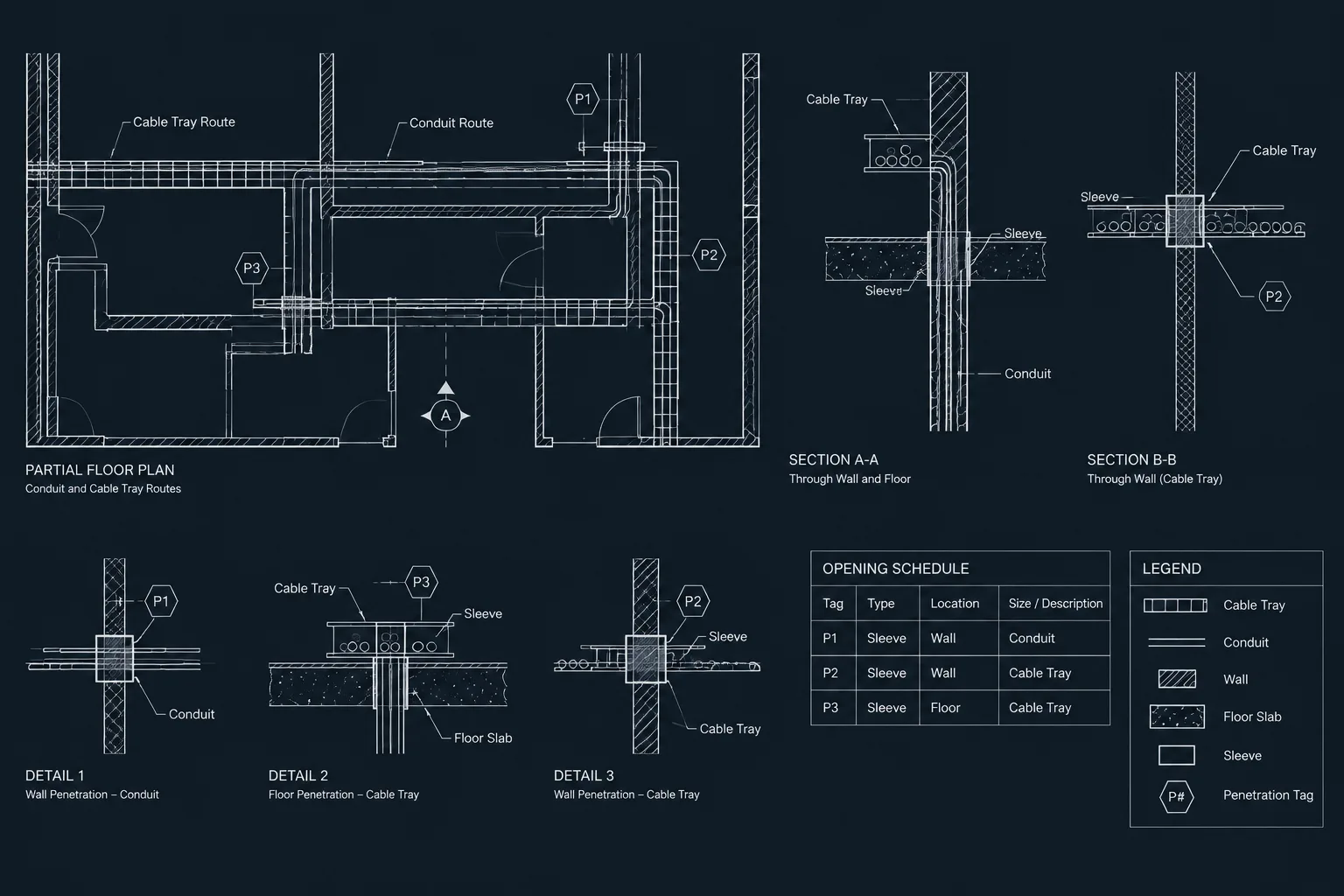
Electrical sleeves and penetrations in CAD must connect pathway geometry with opening locations, identifiers, drawing references, and coordination status. A symbol by itself rarely provides enough information for architectural, structural, and electrical reviewers to understand the intended crossing.
This drawing-reference guide explains how to represent these conditions consistently across plans, sections, details, schedules, and consultant backgrounds. It focuses on CAD documentation and multidisciplinary coordination rather than prescribing construction materials, opening sizes, or installation methods.
Electrical raceways and cables often pass through walls, floors, roofs, foundations, and structural elements. Although these crossings may occupy little space on a plan, they can affect several disciplines and require careful documentation. An unclear sleeve location can lead to misplaced openings, routing conflicts, or uncertainty about who provides the opening and who seals it.
Drafting electrical sleeves and penetrations in CAD is therefore more than placing a circle at a wall. The drawings should communicate the crossing location, intended pathway, opening status, related detail, and coordination responsibility without implying unverified construction requirements. This guide presents a drawing-focused workflow for coordinating those elements across electrical plans, sections, schedules, and consultant backgrounds.
Distinguish the Pathway, Sleeve, and Opening
These terms are related, but they do not always describe the same object:
- Pathway: The conduit, cable tray, busway, cable route, or other system passing through a building element.
- Sleeve: A defined component through which a pathway may pass. Its construction and suitability must be confirmed by the project team.
- Penetration: The condition created where a pathway crosses a wall, floor, roof, or similar assembly.
- Opening: A reserved or constructed void that may accommodate one pathway, multiple pathways, or coordinated services.
A drawing should not use these terms interchangeably unless the project documentation defines them that way. For example, a reserved opening shown on a structural drawing may not represent a fabricated sleeve. Likewise, a conduit crossing a partition may require documentation even when no separate sleeve symbol is used.
Choose the Correct Drawing View
No single view communicates every part of a penetration. Use the view that best answers the coordination question.
Plan views
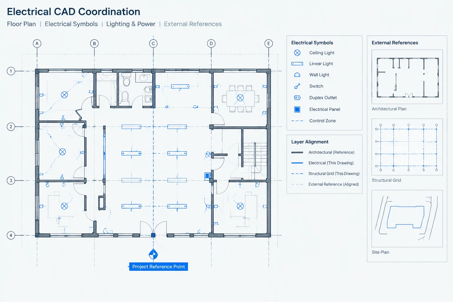
Plans are useful for locating crossings relative to grids, walls, rooms, equipment, and pathway routes. A plan symbol can identify the crossing and connect it to a tag or detail, but it may not clearly show elevation or assembly depth.
Sections and elevations
Sections clarify vertical position, crossing direction, adjacent structure, grouped pathways, and relationships to ceilings or floors. They are especially useful where several routes converge or where the pathway changes elevation near the opening.
Enlarged coordination details
An enlarged detail can separate tightly grouped routes and show which pathway uses each opening. It can also define diagrammatic separation between systems without overcrowding the overall plan.
Schedules
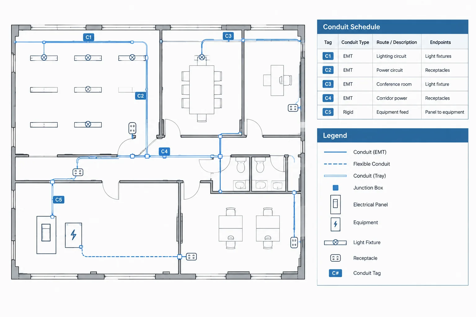
A penetration or sleeve schedule can consolidate identifiers, locations, drawing references, serving systems, status, and coordination remarks. Avoid using a schedule as a substitute for graphical location information; the schedule and drawing should support each other.
Build a Clear Symbol and Tagging System
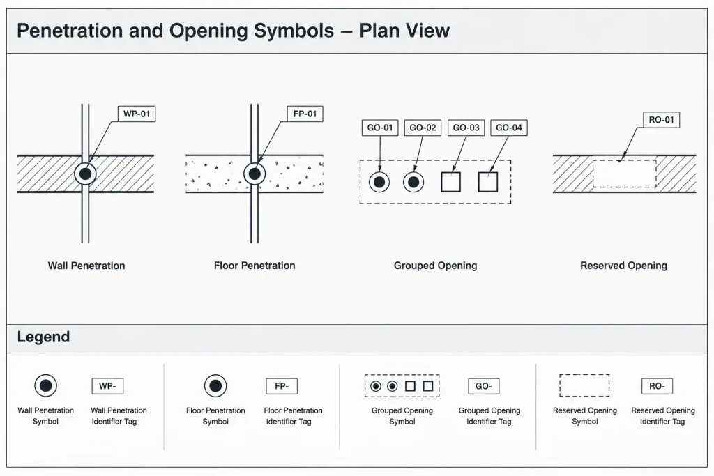
Use a consistent symbol family for horizontal and vertical crossings. The graphics should remain recognizable when plotted, screened over a background, or viewed beside dense architectural and structural linework.
A practical tag may combine a category prefix with a unique identifier. The exact format should follow the project naming convention rather than an improvised numbering system. Keep identifiers stable through revisions whenever possible. Renumbering every opening after one addition makes markups, coordination comments, and field references difficult to trace.
Consider distinguishing the following conditions graphically or through attributes:
- Wall crossing versus floor or roof crossing
- Individual sleeve versus grouped opening
- Reserved opening versus confirmed opening
- Existing opening versus new work
- Opening to remain, modify, relocate, or remove
- Electrical-only route versus shared coordinated opening
Do not rely on color alone to communicate these differences. Linetype, symbol shape, text, or status attributes should preserve meaning in monochrome output.
Use Layers That Separate Intent from Background Geometry
Place sleeve symbols, opening outlines, tags, and penetration notes on controlled electrical layers rather than embedding them in an architectural or structural background. Separate layers may be useful for symbols, identifiers, proposed opening extents, and coordination zones.
The goal is not to create a layer for every possible condition. It is to support common review tasks, such as displaying all penetration tags, isolating unconfirmed openings, or comparing electrical requests with a structural opening plan. Layer names and properties should follow the project CAD standard.
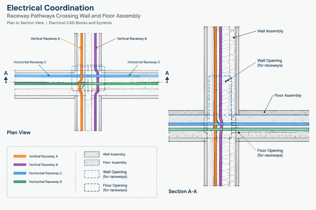
If a structural or architectural consultant provides an opening as background geometry, avoid tracing it without explanation. A duplicate outline can appear to be a second request. Instead, reference the source opening, use a coordinated identifier, or clearly differentiate the electrical request from the consultant’s confirmed geometry.
Coordinate Location in More Than One Direction
A plan coordinate alone may not define a usable crossing. Document enough information to resolve the opening horizontally and vertically. Depending on the drawing set, this may involve grid references, dimensions to stable building elements, level references, sections, elevations, or linked model information.
Dimension to durable references rather than movable objects such as furniture. Avoid chains of dimensions that depend on several intermediate elements. If the architectural wall moves, the electrical penetration request should be reviewed rather than left behind as isolated CAD geometry.
Where an opening serves a routed pathway, check that the route actually intersects the opening in every applicable view. A conduit line that visually stops near a symbol can create uncertainty about whether the crossing is intended or merely adjacent.
Track Status Without Overstating Approval
Penetrations often develop through several coordination stages. CAD documentation should make those stages visible without claiming that a location or detail is approved unless that approval has been formally established.
| Status concept | Drawing meaning | Recommended drafting treatment |
|---|---|---|
| Proposed | Electrical location submitted for coordination | Show with a clear preliminary status attribute or note |
| Under review | Other disciplines are checking the request | Retain the identifier and record the review state |
| Coordinated | Location has been reconciled in the current drawing workflow | Reference the relevant background or coordination record |
| Revised | Location, extent, or serving route changed | Preserve revision traceability and update affected views |
| Deleted | Opening request is no longer required | Remove it from current scope while retaining issue history as required |
Terminology should match the project’s document-control process. Words such as coordinated, accepted, reviewed, and approved can have different contractual meanings, so they should not be used casually.
Create a Useful Penetration Schedule
A schedule can help reconcile plans with structural opening drawings and detail references. Useful fields may include:

- Unique opening or sleeve identifier
- Building level and area
- Wall, floor, roof, or foundation condition
- Electrical system or pathway served
- Source and destination references
- Related plan, section, or detail
- Existing or new status
- Coordination status
- Discipline responsible for associated documentation
- Remarks identifying unresolved constraints
Physical size, material, fire-resistance treatment, structural reinforcement, weatherproofing, and installation requirements should only be included when supported by verified project information. Do not infer these properties from the appearance of a generic CAD block.
Coordinate Fire-Rated and Weather-Exposed Assemblies Carefully
A penetration through a rated assembly or building envelope is not fully documented by an electrical symbol alone. The drawing set may need references to architectural assembly information, approved project details, firestopping documentation, roofing requirements, or waterproofing coordination.
Keep the electrical drawing focused on pathway intent and cross-references. Avoid drafting a generic sealing detail and presenting it as universally suitable. The applicable assembly, penetrating item, opening condition, and project requirements must be verified by qualified project participants.
Manage Changes Across the Drawing Set
When a route moves, search for every representation of its crossing. Update the plan symbol, opening outline, tag, schedule row, section, detail, and consultant coordination markup as applicable. Also check whether the old opening remains visible in an external reference or previously exported background.
Block attributes can help store identifiers and statuses, while extracted data can support a schedule. However, automation does not eliminate review. A block may contain current data while sitting at an obsolete location, or a schedule may retain an identifier for geometry that was deleted manually.
Pre-Issue CAD Review Checklist
- Confirm that each tagged crossing corresponds to an actual electrical route.
- Check that wall, floor, and roof conditions use the intended symbol type.
- Verify that identifiers are unique and match the schedule.
- Review horizontal and vertical location references.
- Compare electrical requests with current architectural and structural backgrounds.
- Confirm that existing, new, relocated, and deleted conditions are distinguishable.
- Check sections and enlarged details for consistency with the plan.
- Identify unresolved opening extents or assembly requirements rather than guessing.
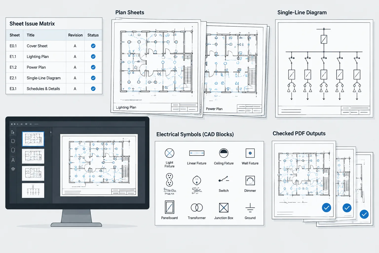
- Test plot the sheet to confirm that symbols and tags remain legible.
- Review revision scope so moved or removed openings are traceable.
A Coordinated Drawing Object, Not Just a Circle
A sleeve or penetration symbol should function as part of a coordinated documentation system. Its value comes from the relationship among the route, location, identifier, status, schedule, section, and supporting detail. When those elements agree, the drawing communicates a clear opening request and supports multidisciplinary review. When they do not, even a neatly drafted symbol can hide a significant coordination gap.
Turn Each Crossing Into a Traceable Coordination Item
A useful penetration record should answer several questions: what passes through the assembly, where the crossing occurs, which views describe it, whether the opening is confirmed, and which unresolved issue requires review. Keeping these answers connected reduces the risk that a route, symbol, and schedule will describe different conditions.
Maintain an issue log alongside the drawing
For complex coordination, use a controlled issue log or extracted block data to track comments that do not belong on the plotted sheet. The log can identify the drawing tag, affected discipline, current background reference, open question, and disposition. It should support the contract documents rather than replace information that must appear on them.
Separate requested geometry from received geometry
An electrical opening request and a consultant-confirmed opening may overlap visually but represent different stages of coordination. Distinguish them through controlled layers, status attributes, or clearly defined symbols. This allows reviewers to compare intent with the current architectural or structural information without mistaking duplicated linework for separate openings.
Review relationships, not only objects
Object-level checks confirm that a block exists and contains an identifier. Relationship-level checks confirm that the pathway reaches the block, the section matches the plan, the schedule contains the same tag, and the background shows the expected assembly. These relationship checks provide greater coordination value than simply counting symbols.
Preserve unresolved conditions honestly
When an opening extent, assembly treatment, or responsibility has not been verified, identify it as unresolved instead of completing the drawing with assumed information. A visible coordination note is more useful than a polished detail that incorrectly suggests final approval or technical suitability.
Frequently Asked Questions
Is a sleeve symbol enough to document a penetration?
Usually not. The symbol should be connected to a pathway, stable location reference, identifier, status, and any applicable section, detail, or schedule entry. The required documentation depends on the project drawing workflow.
Should electrical drawings show openings supplied by another discipline?
They may show or reference those openings when needed for coordination, but the graphics should identify their source and avoid implying duplicate scope. Confirmed background geometry should remain distinguishable from an electrical request.
Can a generic CAD block define the required sleeve construction?
No. A generic block can communicate location, orientation, category, or status, but it does not establish material, assembly compatibility, sealing treatment, or structural requirements. Those properties require verified project information.
How should relocated penetrations be handled?
Update every connected representation, including route geometry, tags, schedules, sections, details, and coordination records. The previous condition should be managed through the project’s revision and document-control process rather than left as unexplained geometry.
Why should color not be the only status indicator?
Color distinctions can disappear in monochrome plots, screened backgrounds, exports, or different display settings. Pair color with text, symbol shape, linetype, or an attribute so the intended meaning remains readable.
What should be checked when a pathway crosses a rated or weather-exposed assembly?
The electrical documents should identify the pathway intent and reference the applicable coordinated information. Assembly treatment, firestopping, roofing, waterproofing, and related construction requirements should not be inferred from a generic penetration symbol.






Leave a Reply
You must be logged in to post a comment.