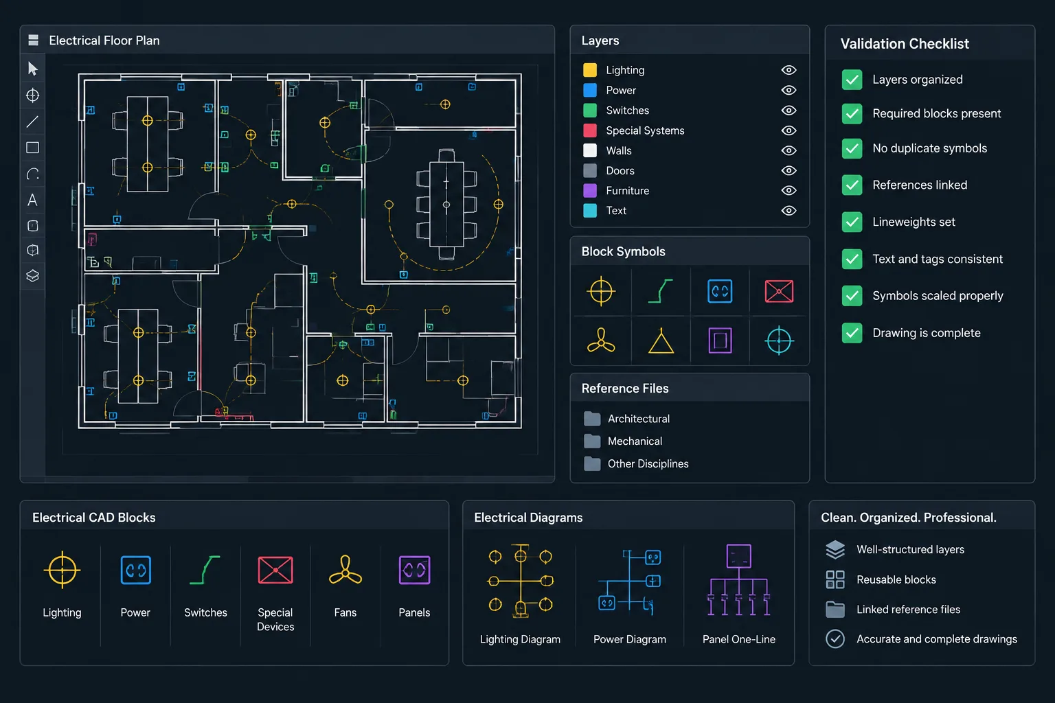
Electrical CAD file health depends on more than file size or whether a drawing opens without an error message. Blocks, attributes, layers, external references, layouts, and plotting resources must remain coordinated so the drawing continues to function as both a design file and a project document.
This guide presents a platform-neutral workflow for diagnosing drawing problems, removing unnecessary data cautiously, and checking the result. Apply each step through the commands and revision procedures approved for your CAD platform and project environment.
Electrical CAD file cleanup is not simply a matter of making a DWG smaller. A healthy drawing should open reliably, retain the information required for the project, coordinate with referenced files, and produce the intended plotted result. Cleanup must therefore be controlled, especially when a file contains electrical symbols, equipment tags, circuit annotations, external references, schedules, or data-bearing blocks.
Unplanned purging can remove resources that were intentionally prepared for future sheets. Aggressive repair can alter objects without resolving the underlying problem. A better approach separates diagnosis, correction, removal, and final validation. The goal is a dependable project file, not merely an empty list of unused definitions.
What File Health Means in an Electrical Drawing
File health covers several related conditions. A drawing may appear normal on screen while still containing unresolved references, duplicate definitions, damaged objects, excessive imported content, or plotting inconsistencies.
For electrical documentation, a healthy file should generally have:
- Predictable opening, saving, and plotting behavior.
- Valid connections to required architectural, structural, civil, and consultant backgrounds.
- Consistent electrical layers, blocks, text styles, dimensions, and annotation resources.
- Readable plans, diagrams, schedules, and details in their intended sheet views.
- No unexplained proxy content, missing fonts, or unresolved linked resources.
- No unnecessary imported definitions that obscure the project standard.
- Preserved block attributes and equipment identifiers where they carry project data.
A large file is not automatically unhealthy, and a small file is not automatically clean. Complexity may be legitimate when a project includes detailed backgrounds, multiple layouts, embedded schedules, or extensive equipment information.
Audit Before You Purge
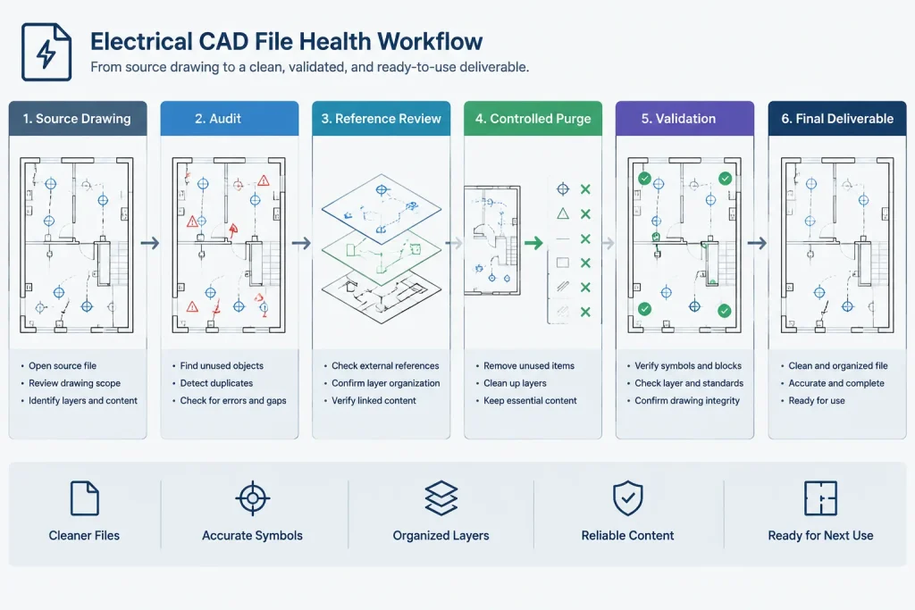
Begin with investigation rather than deletion. Work on a controlled copy when the source file is part of an active project or formal issue set. Record the original file size, reference status, visible warnings, and any known plotting problems so that the result can be compared with the starting condition.
Review the file structure
Inspect model space, sheet layouts, viewports, referenced drawings, images, underlays, and other linked content. A file that appears empty in model space may still support sheet details, legends, or schedules. Likewise, apparently unused layers may be visible only in a particular viewport or design phase.
Check whether the drawing is a working model, a sheet file, a detail file, a background, or a library source. The correct cleanup strategy depends on that role. Removing unused symbols from a project sheet may be reasonable, while purging the same definitions from a shared electrical block library could defeat the purpose of the file.
Run the platform’s drawing audit or validation process
Most professional CAD platforms provide a way to inspect the drawing database and identify invalid or damaged records. Command names and repair behavior vary, so review the reported findings rather than assuming that every correction is harmless.
After an audit, save the file under controlled revision practices and reopen it. Repeated errors can indicate that a referenced drawing, imported object, third-party object type, or automation routine is recreating the problem.
Classify Unused and Suspicious Content
Before removing anything, classify it by purpose. This prevents legitimate project resources from being mistaken for clutter.
| Content type | Questions to ask | Typical concern |
|---|---|---|
| Electrical blocks | Are they inserted, nested, scheduled, or reserved by the template? | Purging can remove approved office symbols needed later. |
| Layers | Are they used in viewports, block contents, referenced files, or phase controls? | An apparently empty layer may support hidden block geometry or sheet-specific visibility. |
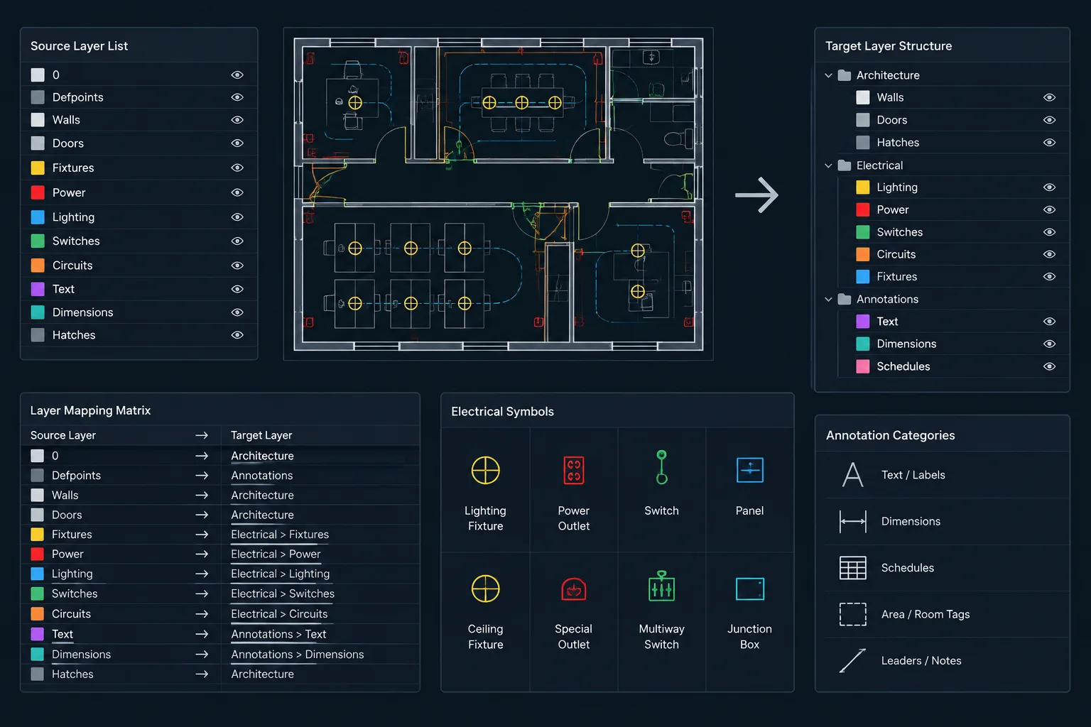
| Text and dimension styles | Are they required by layouts, annotative objects, details, or client standards? | Imported styles can create duplicates, but project styles must remain stable. |
| Line types and plot resources | Do they communicate existing, concealed, overhead, or demolition conditions? | Substitution can change the meaning or readability of electrical linework. |
| External references | Are they current, intentionally unloaded, or obsolete? | Removing an unloaded reference may break a planned coordination workflow. |
| Registered or application data | Does a project tool, block library, or data-extraction process rely on it? | Blind removal may affect downstream automation or object behavior. |
Suspicious content is not always unused. For example, anonymous or system-generated definitions may belong to dimensions, hatches, dynamic symbols, or imported objects. Do not delete unfamiliar records solely because their names are unclear.
Use a Controlled Purge Sequence
Purging removes definitions that the drawing database considers unreferenced. It should follow an audit and content review, not replace them. A staged sequence makes changes easier to understand and reverse.
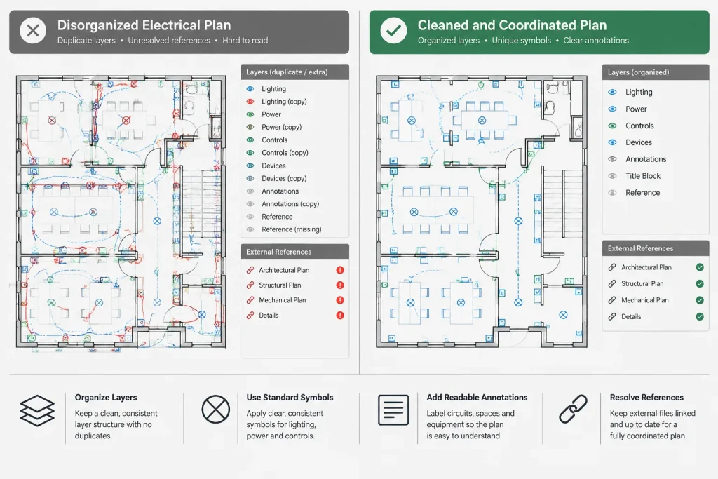
- Resolve required references. Confirm which backgrounds and linked resources belong to the project. Correct approved paths or reference assignments before judging other content.
- Remove known temporary geometry. Delete abandoned sketch lines, copied markups, test symbols, isolated notes, and unused construction geometry only after confirming that they are not part of the deliverable.
- Review duplicate or imported standards. Identify layers, blocks, and styles brought in from vendor files or consultant backgrounds. Rename, map, retain, or remove them according to the project workflow.
- Purge by category. Review blocks, layers, line types, text styles, dimension styles, and other definitions separately where the software allows it. Category-based review provides more control than removing everything at once.
- Repeat only when justified. Nested definitions may become unused after a parent definition is removed. Review subsequent purge results rather than treating repeated purging as an automatic objective.
Do not use purging to hide unresolved coordination issues. A missing background, broken font, or invalid object type requires investigation even if the drawing can still be saved.
Look for Electrical-Specific Cleanup Risks
Attributes and equipment data
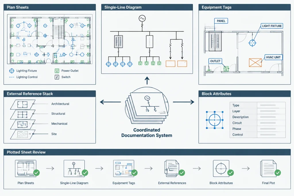
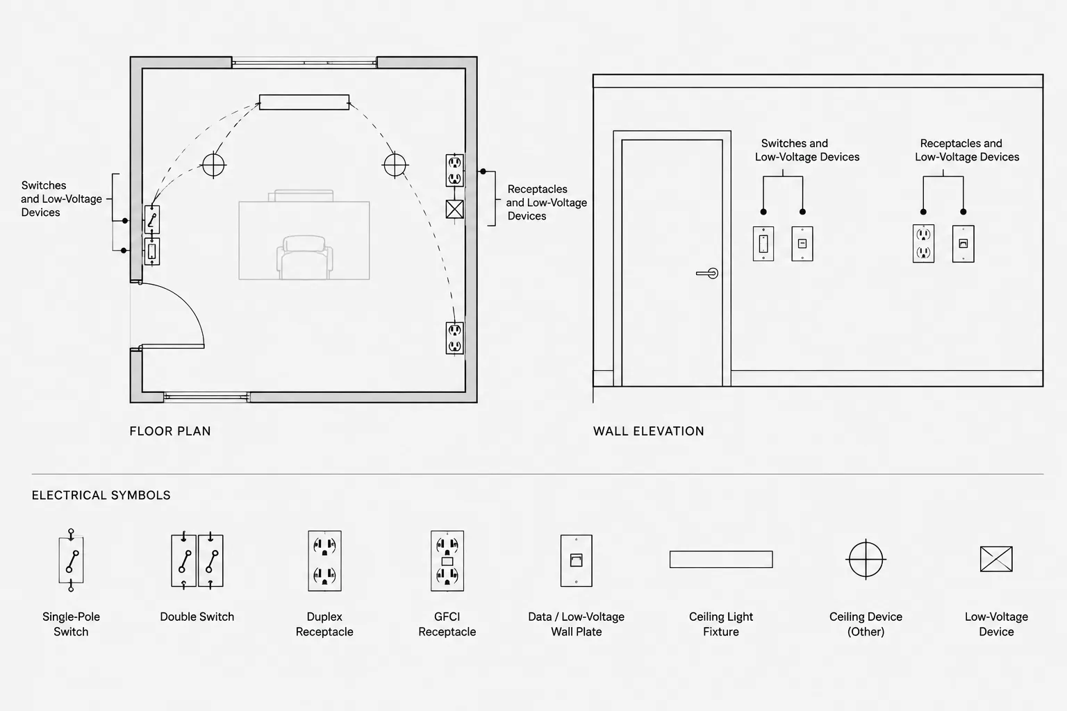
Electrical blocks often contain tags, circuit identifiers, panel names, fixture types, or equipment references. A symbol that looks correct may carry hidden attributes used for schedules or data extraction. Confirm that cleanup has not reset values, replaced attributed blocks with plain geometry, or separated tags from their associated devices.
Nested symbols
A device block may contain nested graphics for connection points, status marks, mounting notation, or discipline-specific components. Editing or redefining the parent block can affect every occurrence. Compare representative symbols before and after cleanup, including rotated and mirrored examples.
Diagram connectivity
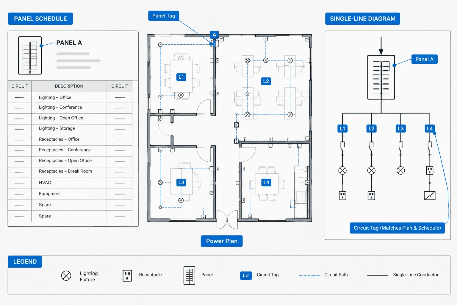
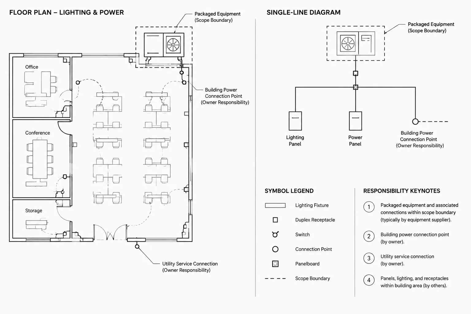
Single-line diagrams, risers, schematics, and interconnection drawings depend on visual continuity. Check that lines still meet device connection points and that cleanup has not removed short segments, junction indicators, off-sheet references, or masked portions of conductors.
Viewport-dependent content
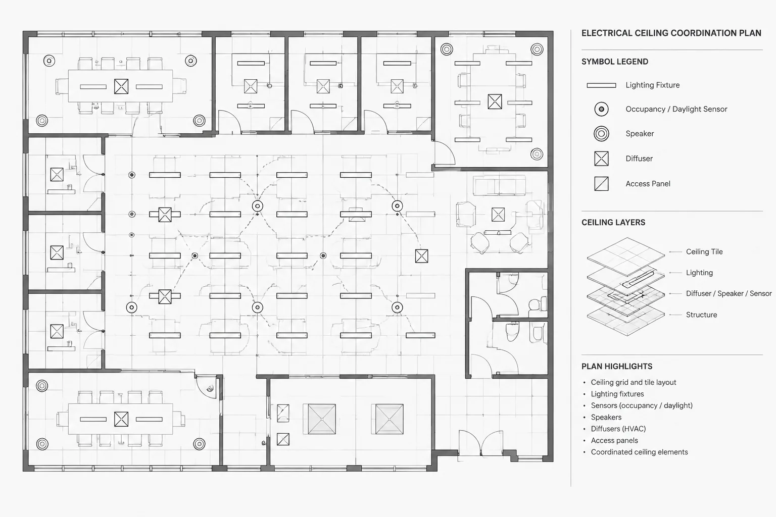
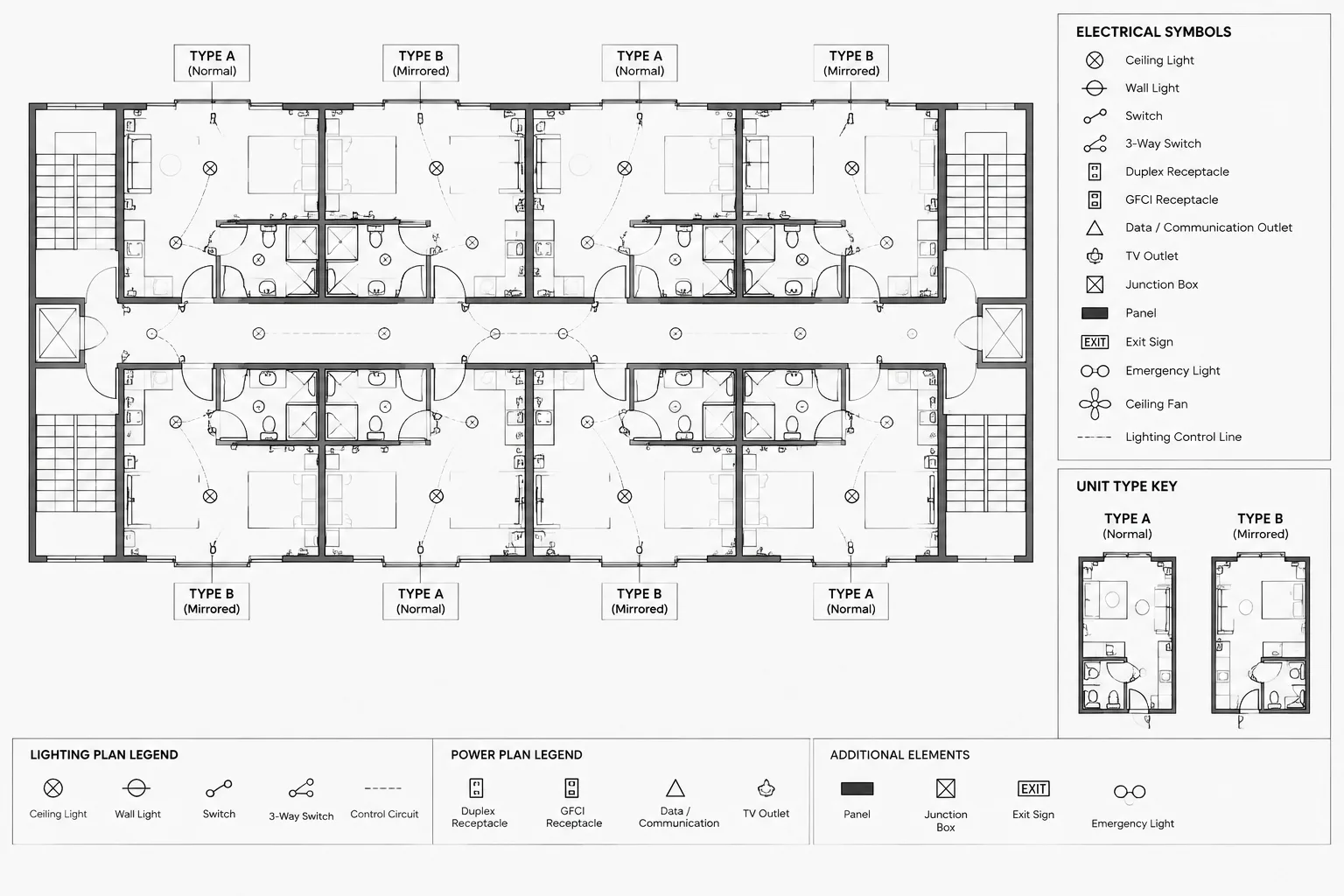
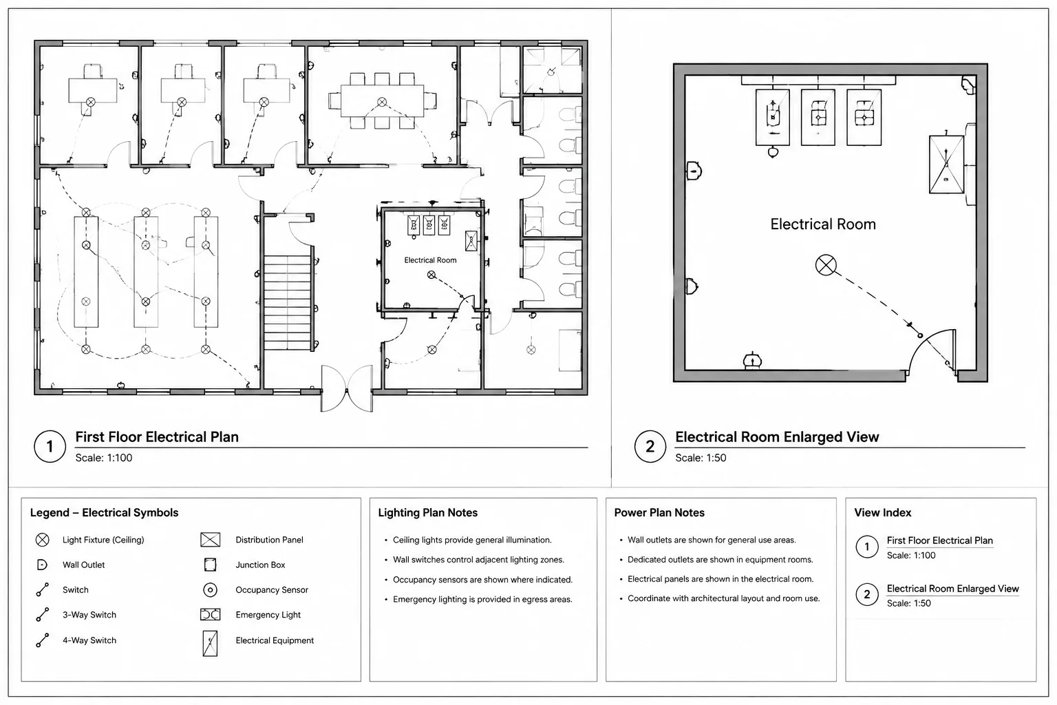
Electrical sheets may use viewport layer controls to create lighting, power, demolition, or enlarged views from related model geometry. A layer that appears unnecessary in the active view may be essential elsewhere. Review every layout and saved sheet view before deleting layer definitions.
Repair References Instead of Embedding Everything
Missing references often tempt users to bind, explode, or copy all background geometry into the host drawing. That may produce a self-contained file, but it can also introduce duplicate layers, block-name conflicts, excessive detail, and unclear ownership of consultant information.
First determine whether the file is intended for active coordination, archival delivery, or external exchange. Active project files generally benefit from controlled references because updates remain traceable. A required handoff may call for a different packaging method, but that decision should follow the project’s documented deliverable rules.
When a reference is obsolete, detach it only after confirming that no sheet depends on its geometry. Unloading and detaching are not interchangeable: an unloaded reference may be intentionally retained for later use, while a detached reference is removed from the host file’s reference structure.
Validate the Cleaned Drawing
A cleanup is incomplete until the output has been tested. Reopen the file and examine it as a document rather than only as a CAD database.
- Open each layout and allow viewports and references to display.
- Compare representative electrical plans with the previous controlled version.
- Check legends, schedules, panel references, and equipment tags.
- Inspect single-line and riser continuity at connection points.
- Confirm that required fonts, line types, symbols, and hatches display correctly.
- Plot or publish a review copy using the intended project settings.
- Check that lineweights, screening, masks, and background contrast remain legible.
- Run the drawing audit again and review any remaining messages.
Visual comparison is especially important because database cleanup can be technically successful while changing the plotted document. A missing symbol definition, altered font, or failed mask may not be obvious until a sheet is published.
Create a Repeatable File-Health Record
For project teams, cleanup should be documented briefly. Record the file name, date, reason for cleanup, major actions, unresolved warnings, and validation performed. If definitions were intentionally retained, note why. This gives the next drafter context and discourages repeated, aggressive cleanup.
File health is best maintained throughout production rather than addressed only before handoff. Controlled imports, disciplined reference management, consistent block sources, and periodic validation reduce the need for emergency repairs. The most reliable electrical CAD file is not the one with the fewest definitions; it is the one whose contents are understood, coordinated, and reproducible in the issued drawing set.
Match the Cleanup Response to the Symptom
Different symptoms point to different parts of the drawing environment. Treating every problem as excess data can conceal the actual cause.
- Slow opening or regeneration: Review reference loading, imported geometry, proxy objects, complex hatches, and repeated content before assuming that the drawing database is damaged.
- Unexpected visual changes: Check fonts, line types, plot resources, viewport overrides, annotation settings, and referenced-file revisions.
- Errors that return after repair: Investigate linked drawings, imported objects, third-party object types, templates, and automation processes that may recreate the affected records.
- Incorrect schedules or extracted data: Examine block attributes, equipment identifiers, nested definitions, and field relationships rather than relying only on the visible symbol.
- Problems limited to publishing: Compare model display with layout output and review masks, screening, lineweights, background contrast, and plot configuration.
Retain Evidence of the Cleanup
A controlled cleanup should leave enough information for another project team member to understand what changed. Keep the untouched source under the applicable revision procedure, identify the cleaned working copy clearly, and retain a review plot or comparable output when document appearance is important.
The record should distinguish corrected database errors from intentionally removed resources. It should also identify unresolved warnings, missing dependencies, or specialized objects that require review in their authoring application. This prevents a later user from interpreting an incomplete repair as a fully validated deliverable.
Use File Size as a Clue, Not a Verdict
A reduction in file size may show that unused definitions or temporary objects were removed, but it does not prove that the drawing is healthy. Conversely, little or no reduction does not mean the cleanup failed. The stronger indicators are stable opening and saving, resolved project dependencies, preserved electrical data, and consistent published output.
Frequently Asked Questions
What is the difference between auditing and purging a CAD drawing?
Auditing examines the drawing database for invalid or damaged records and may offer corrections. Purging removes definitions the software considers unreferenced. Because these processes address different conditions, an audit should not be treated as a substitute for a purge or vice versa.
Can purging remove electrical symbol data?
A standard purge is intended to target unreferenced definitions, but drawing relationships can be difficult to recognize. Symbols may be nested, reserved by a template, associated with application data, or used by extraction workflows. Review categories and preserve a controlled source copy before removal.
Why do drawing errors return after a successful audit?
The affected data may be reintroduced by an external reference, imported object, specialized application object, template, or automation routine. Repeated errors are a reason to investigate the source process rather than repeatedly repairing only the host file.
Should missing external references be bound into the drawing?
Not automatically. Binding may be appropriate for a documented handoff workflow, but it can also introduce duplicate definitions and reduce update traceability. First determine whether the reference should be restored, repathed, unloaded, detached, or packaged according to the project requirements.
How can a drafter confirm that cleanup did not damage the electrical drawing?
Reopen the cleaned file, review layouts and references, inspect representative symbols and attributes, check diagram continuity, and publish a review output. Compare that output with the controlled source and investigate any unexplained difference before accepting the file.
Leave a Reply
You must be logged in to post a comment.