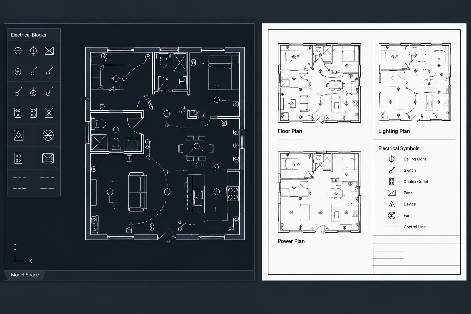
Model space vs. paper space in electrical CAD is more than a plotting choice. It determines where coordinated design information is maintained, how that information is presented on sheets, and how reliably revisions carry through a drawing set.
This reference explains how to separate electrical geometry from sheet presentation, manage viewport-dependent displays, place annotations consistently, and review layouts before publication. Project templates and client requirements should govern the final workflow.
One of the most important organizational decisions in an electrical CAD project is deciding what belongs in model space and what belongs in paper space. The distinction affects drawing scale, annotation, coordination, plotting, file maintenance, and the way other users navigate the finished DWG files.
A dependable workflow does not treat the two environments as interchangeable. Model space generally holds project geometry and coordinated electrical information, while paper space assembles that information into publishable sheets. The exact division may vary with a client standard or project template, but it should be deliberate and consistent.
What model space and paper space represent
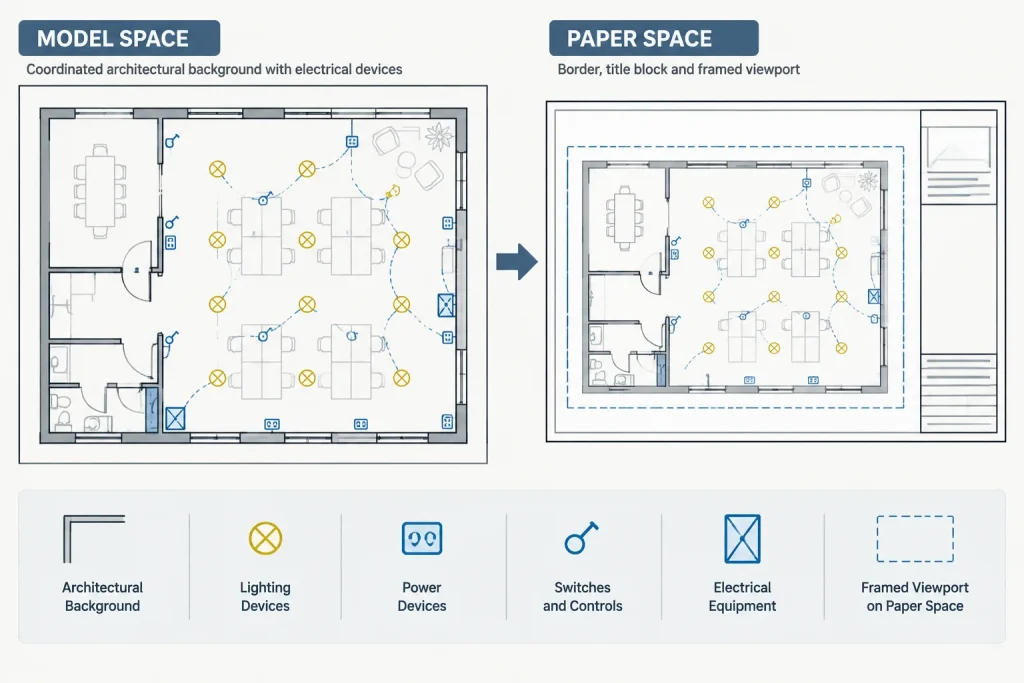
Model space is the primary drafting environment for plans, equipment layouts, routes, and diagrams. Plan geometry is normally drawn at its actual project size using the drawing units established for the job. Electrical symbols are then placed in relation to the architectural or civil background rather than resized to imitate a printed sheet.
Paper space, also called a layout environment, represents the final sheet. It contains the sheet boundary and provides windows, commonly called viewports, through which selected areas of model space are displayed. Each viewport can show a particular area, layer configuration, orientation, and plotting scale.
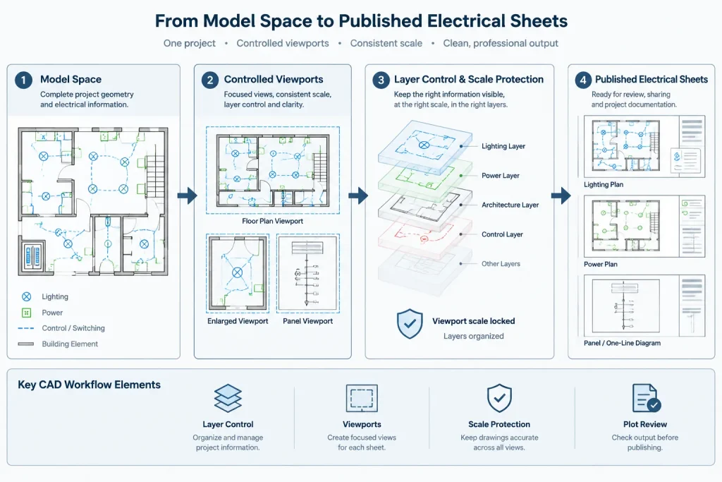
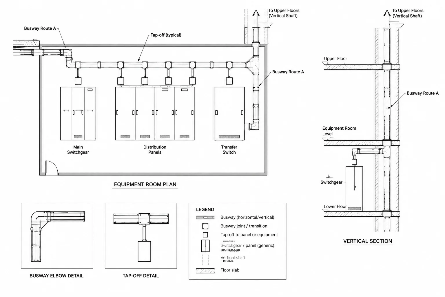
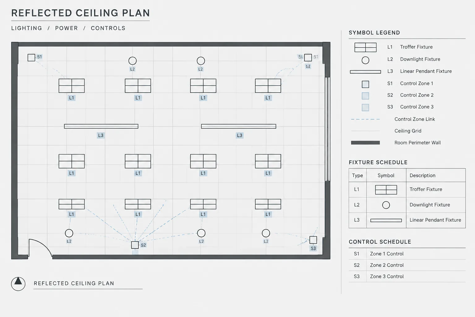
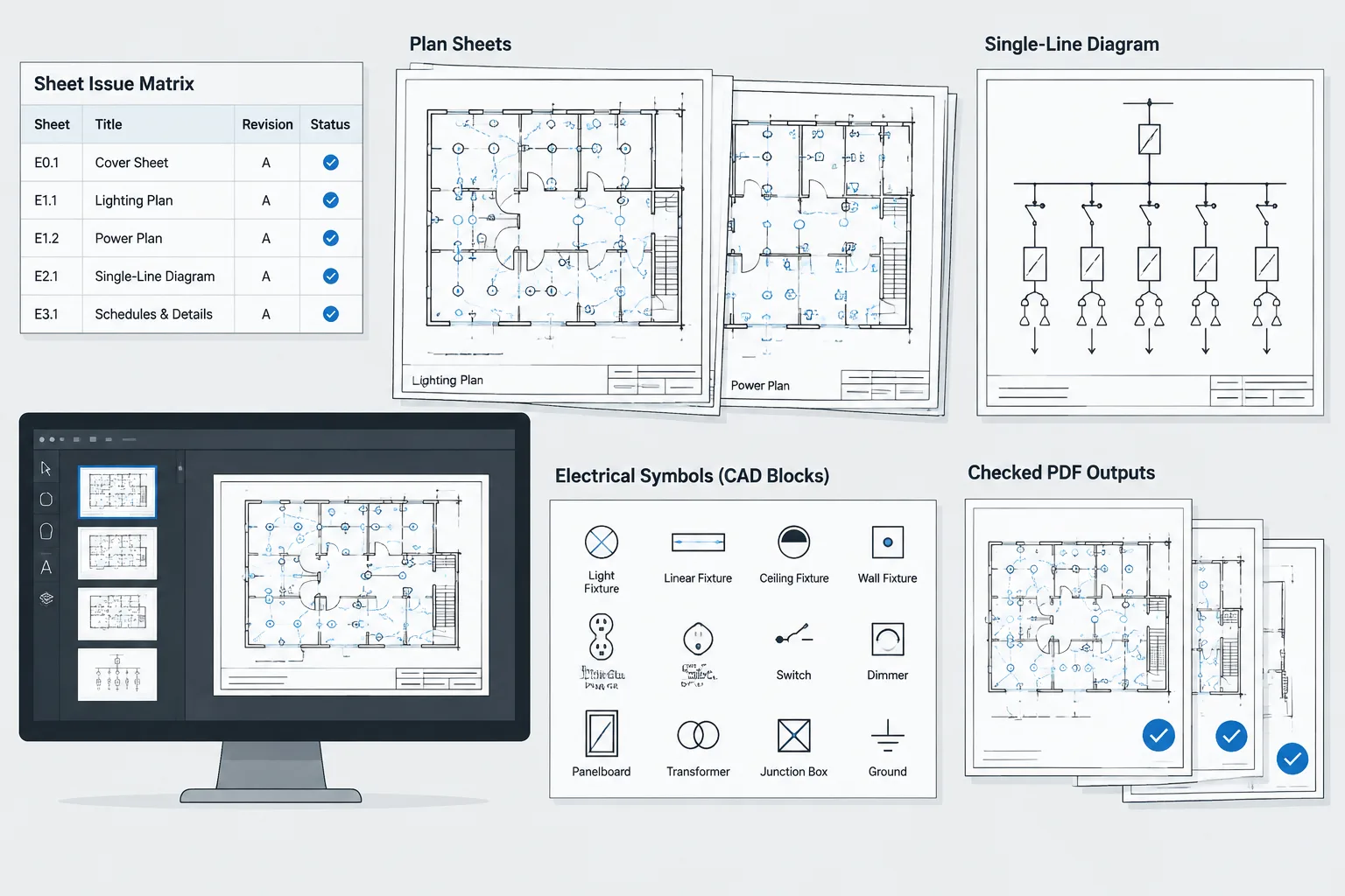
This arrangement separates the coordinated design model from its sheet presentation. A floor plan can exist once in model space while several layouts show an overall power plan, an enlarged electrical room, a demolition view, or a phased construction area.
A practical division of drawing content
| Drawing content | Typical location | Reason |
|---|---|---|
| Architectural, structural, civil, or reflected-ceiling backgrounds | Model space, often as references | They establish the coordinated project location and drawing units. |
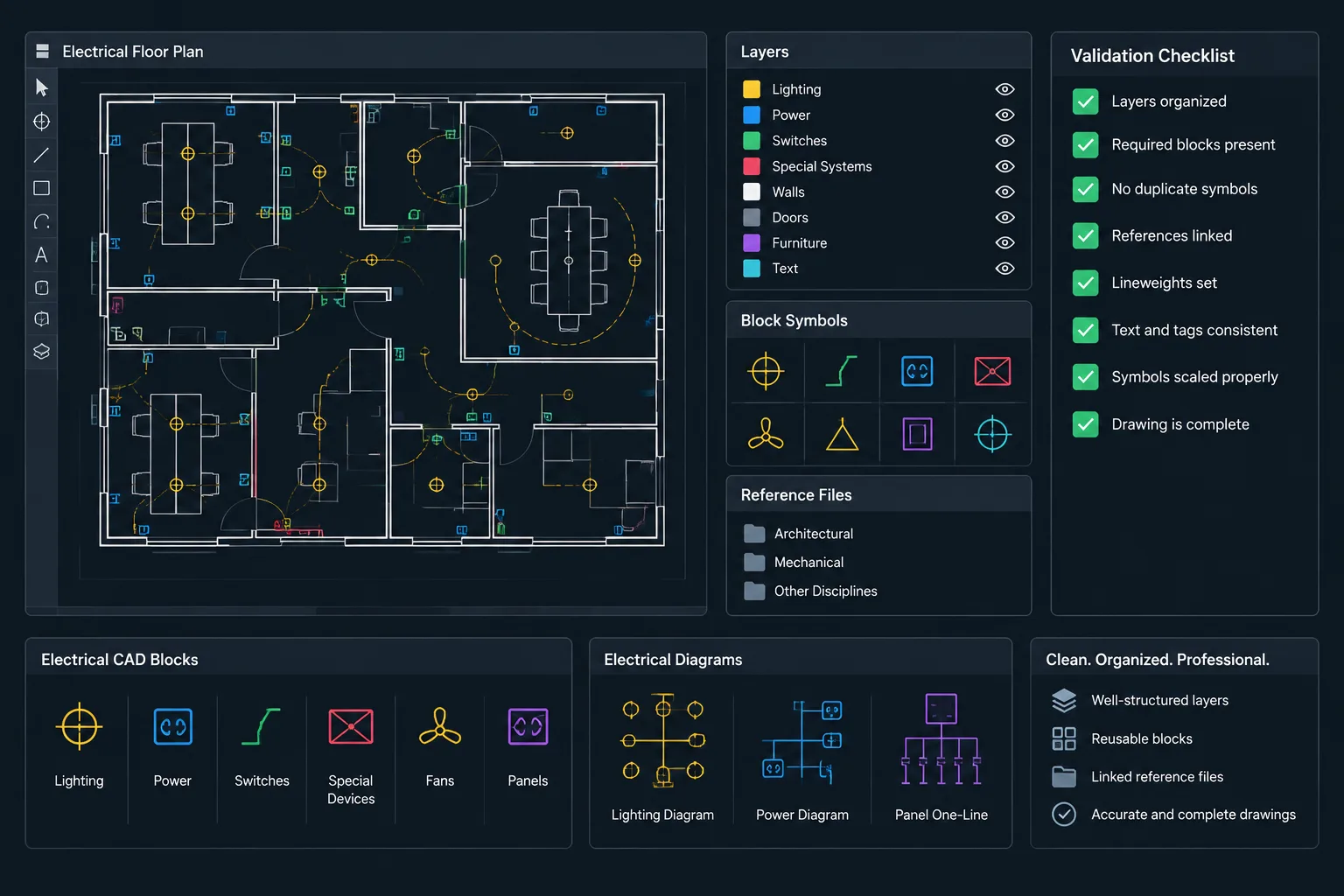
| Electrical devices, fixtures, equipment footprints, and routes | Model space | They need to align with the building and with one another. |
| Single-line, riser, control, and connection diagrams | Usually model space | Keeping diagram objects together supports editing, reuse, and systematic layout. |
| Sheet border and title block | Paper space | These elements describe the published sheet rather than physical project geometry. |
| Viewports | Paper space | They define which model-space information appears on each sheet. |
| Sheet title, sheet number, issue data, and layout-specific approvals | Paper space | The information belongs to a particular sheet or issue. |
| General notes and legends | Depends on project strategy | Reusable content may be maintained centrally, while sheet-specific content may belong in the layout. |
| Viewport titles and graphic scales | Often paper space | They identify and describe a particular plotted view. |
This table describes a common arrangement, not a universal rule. Existing client files may use another convention. Before relocating content, review the project template, plotting method, reference structure, and delivery requirements.
Why electrical geometry usually belongs in model space
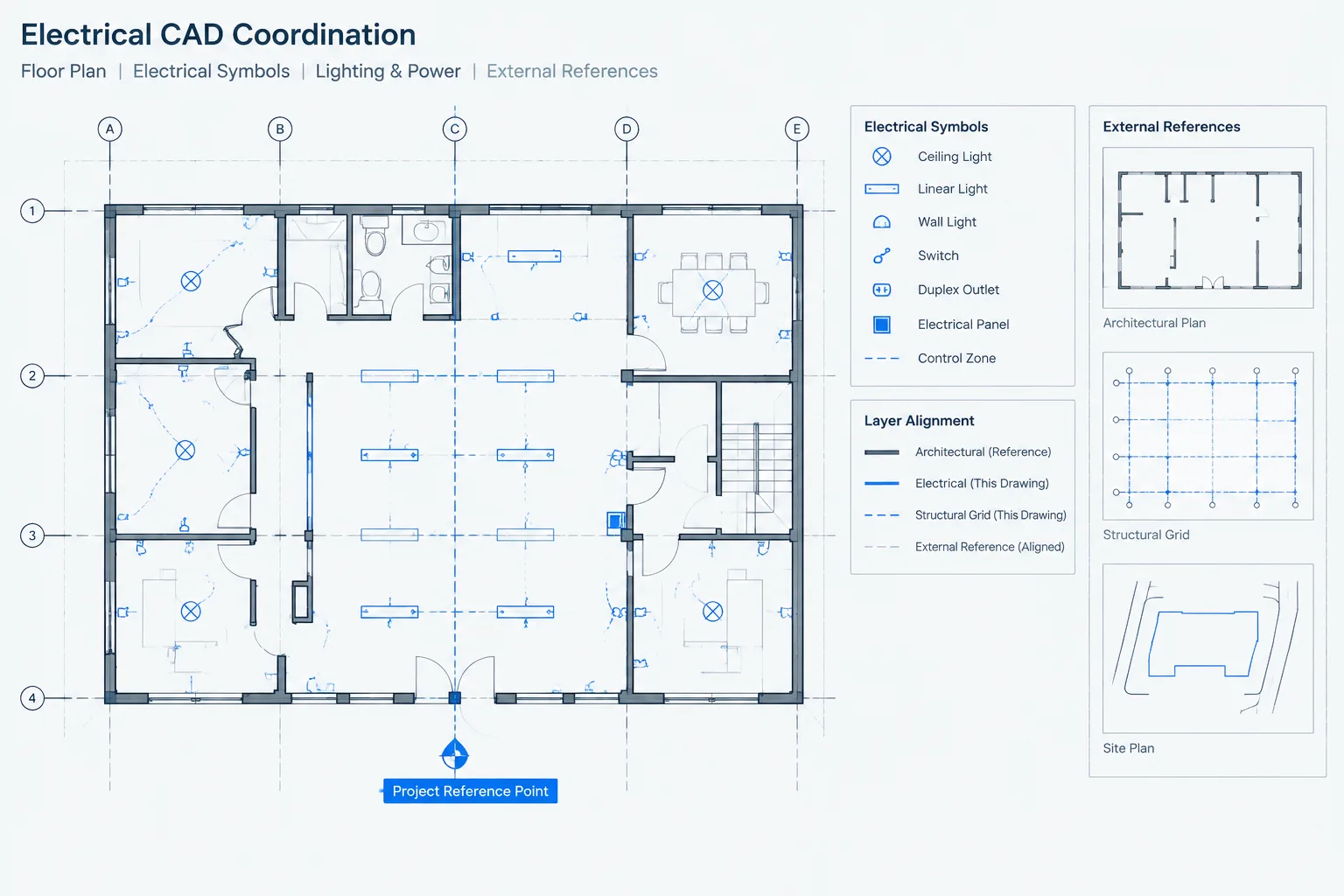
Electrical plan information gains meaning from its relationship to other disciplines. A receptacle is associated with a wall or furniture location. A light fixture relates to a ceiling system. A panel or transformer must coordinate with a room and nearby equipment. Raceway routes and underground utilities rely on shared project coordinates.
Placing this geometry in model space preserves those relationships. It also allows one coordinated arrangement to support multiple sheet views. If electrical symbols are copied separately into paper-space layouts, revisions can produce conflicting versions of the same design.
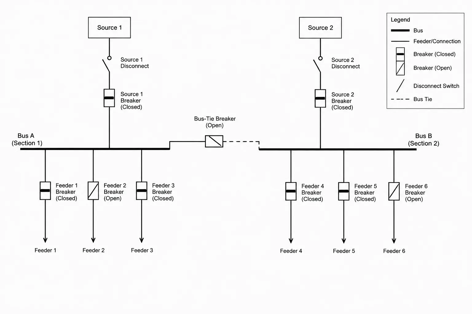
Diagrams do not represent physical floor-plan distances in the same way, but they can still benefit from model-space organization. Sources, buses, feeders, loads, device tags, and cross-references can be maintained in a dedicated diagram area or file. Paper-space viewports then frame the required portions for individual sheets.
Using viewports as controlled presentation windows
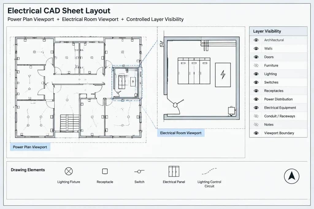
A viewport should be treated as a controlled sheet component, not merely as a hole cut into a layout. It determines what the reader sees and how the view is presented.
Set a clear view boundary
Frame the intended floor area, diagram segment, or enlarged plan without leaving large amounts of irrelevant geometry visible. Coordinate the boundary with match lines, key plans, section references, and adjacent sheets where applicable.
Establish and protect the view scale
After setting the required plotting scale, protect the viewport from accidental zoom changes. An unintended scale change can affect text appearance, symbol readability, dimension interpretation, and the accuracy of graphic scales. The actual scale selected must come from the project’s sheet strategy rather than from an assumed default.
Control layers by view
Different electrical sheets may use the same model while showing different information. A lighting view might suppress power circuiting, while an enlarged equipment-room view may display coordination layers hidden on the overall plan. View-specific layer control can reduce duplicate geometry, but it must be documented so users understand why an object appears in one viewport and not another.
Check clipped and rotated views
Clipped viewports can help fit irregular plan areas onto a sheet, and rotated views can improve sheet use. Both require careful review. Confirm that directional references, room labels, circuit tags, leaders, and text remain understandable. The model geometry should retain its coordinated project position even when its sheet presentation is rotated.
Choosing where annotations belong
Annotation placement is often the most difficult part of the model-space versus paper-space decision. Notes, tags, dimensions, and leaders may refer either to model geometry or to a particular sheet view.
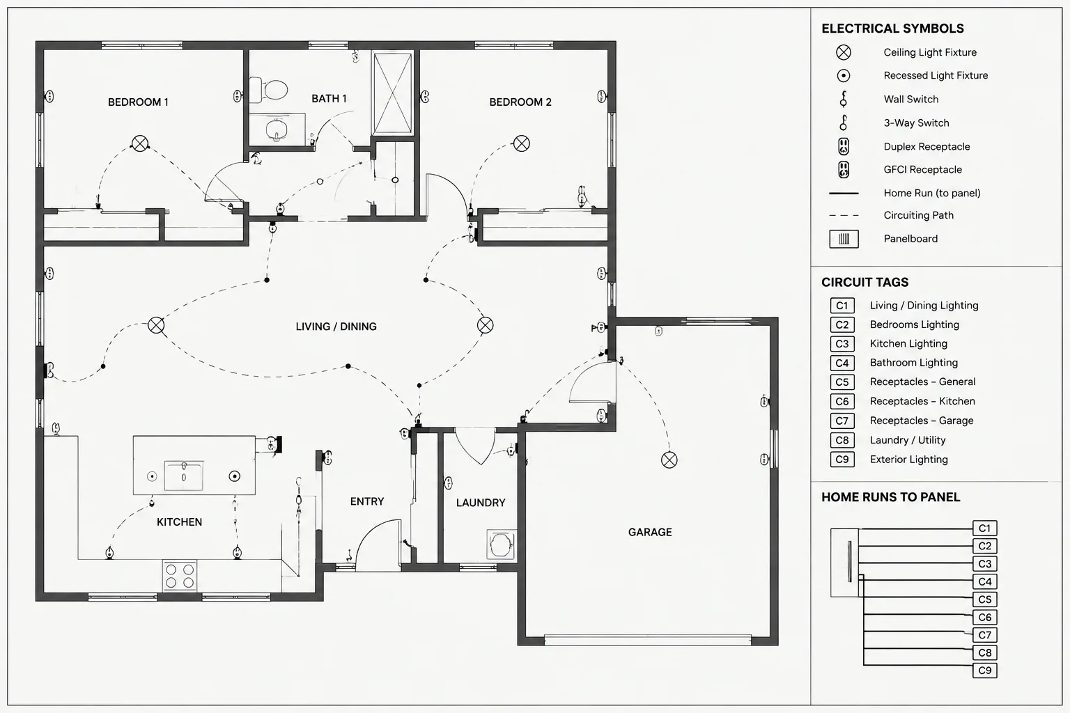
A useful test is to ask: Would this annotation still be valid if the same geometry appeared on another sheet? If so, model space may be appropriate. Device tags, circuit identifiers, equipment IDs, and dimensions tied to project objects often fall into this category. If the note exists only to explain a specific sheet presentation, paper space may be better.
Whichever method is selected, avoid maintaining duplicate annotations in both locations. Duplicate tags can drift apart during revisions. Also verify how text height, leader scale, dimensions, and symbol graphics respond in every viewport where they appear. A note that reads well in one enlarged view may overlap other content in an overall plan.
A disciplined setup workflow
- Confirm units and project coordinates. Resolve the drawing unit convention and reference origin before placing electrical content.
- Review the required sheet list. Identify overall plans, enlarged plans, diagrams, schedules, details, and presentation scales.
- Organize model-space work areas. Separate coordinated floor-plan geometry from diagrams or non-plan details using files, references, or clearly managed drawing regions.
- Create layouts from the approved template. Use the correct border, title block fields, plot configuration, and issue-data method.
- Create and name viewports logically. A recognizable naming or layer convention makes viewport boundaries easier to manage.
- Assign view-specific visibility. Show only the backgrounds, electrical systems, notes, and coordination layers needed for that sheet.
- Set and protect scales. Verify each viewport after framing the view, then prevent casual navigation from changing it.
- Add sheet-dependent graphics. Place sheet titles, viewport titles, graphic scales, and layout-specific notes according to the project standard.
- Plot-test the complete sheet. Review lineweights, text, masks, clipping, reference visibility, and raster or PDF output rather than relying only on the editing display.
Common organization problems
- Drawing the border in model space: This can entangle sheet size with project geometry and encourage scaling of the model to fit a page.
- Copying the same plan for every sheet: Separate copies make coordinated revisions difficult and can conceal differences between plans.
- Leaving viewport boundaries on printable layers: Unwanted rectangular or clipped outlines may appear in the issued PDF.
- Using paper-space symbols to patch a model: The sheet may look correct while the actual coordinated geometry remains incomplete or misplaced.
- Changing model geometry to improve one viewport: Moving a device or diagram element solely for one sheet can damage other views. Consider view-specific annotation or a dedicated detail strategy instead.
- Mixing annotation methods without rules: Users may not know where to edit a tag, and duplicated information can survive unnoticed.
- Failing to inspect every layout: A reference reload, layer change, or model edit can affect several sheets at once.
Quality-control checks before publishing
Review both the model and the assembled layouts. In model space, confirm that electrical objects align with current backgrounds, blocks retain their intended properties, and diagram relationships remain complete. In paper space, confirm that every viewport shows the correct area, orientation, scale, and layer state.
Plot or export the entire sheet set and examine the published files. Look for missing references, inconsistent lineweights, unreadable tags, cropped leaders, visible viewport frames, incorrect sheet fields, and notes hidden beyond viewport boundaries. Where plans and diagrams share identifiers, verify that viewport organization has not concealed conflicting equipment or circuit tags.
The best model-space and paper-space workflow is not the one with the most elaborate setup. It is the one that lets a project team edit information once, present it clearly in several contexts, and reliably reproduce the intended electrical drawing set.
Use ownership to resolve uncertain placement
When the correct location for an object is unclear, identify what owns the information. Content owned by the coordinated design generally belongs with the model. Content owned by a particular sheet, issue, or plotted view generally belongs with the layout.
This ownership test is especially useful for electrical drawing elements that appear similar but serve different purposes. An equipment identifier associated with the design object may need to remain available across several views, while a viewport title describes only the sheet presentation. Likewise, a route belongs to the coordinated electrical layout, but a note explaining why part of that route is emphasized may apply only to one published view.
Consider downstream users
A well-organized file should remain understandable to someone who did not create it. Drafters should be able to locate the editable source of a symbol or note without searching through overlapping model and layout content. Reviewers should be able to distinguish design information from sheet-composition graphics. Plotting staff should be able to publish layouts without changing model geometry.
Consistent object placement also improves drawing handoff. Clear layer names, recognizable viewport controls, stable references, and documented annotation rules help reduce accidental edits when files move between team members or disciplines.
Treat layouts as documented views of one coordinated source
Paper-space layouts should communicate selected views of the electrical information rather than become independent copies of that information. If a layout requires a visual exception, document whether the exception is created through viewport visibility, sheet-specific annotation, or a dedicated detail. This makes later revisions easier to trace.
Before issuing the drawing set, compare the published output with the current model rather than checking layouts in isolation. A sheet can appear complete while hiding outdated, duplicated, or misplaced model content. Reviewing both environments helps confirm that the presentation and its coordinated source remain aligned.
Frequently asked questions
Should electrical symbols be placed in model space or paper space?
Symbols representing fixtures, devices, equipment, or coordinated routes generally belong in model space because they relate to project geometry. Symbols used only as sheet graphics may belong in paper space. The project template and documented drafting standard should control the final choice.
Can the same model-space plan appear on several electrical sheets?
Yes. Separate layouts and viewports can present different areas, layer states, orientations, or levels of detail from the same coordinated model. This avoids maintaining independent copies of the plan.
Where should electrical notes and tags be placed?
Place annotations according to what they describe. Information tied to a design object may be maintained with the model, while sheet-specific directions and viewport titles may be better suited to paper space. Avoid duplicating the same annotation in both environments.
Why should viewport scale and visibility be protected?
Uncontrolled viewport changes can alter the displayed area, annotation appearance, layer visibility, and relationship between the view and its graphic scale. Protecting reviewed viewport settings helps preserve the intended sheet presentation.
Does paper space replace model-space coordination?
No. Paper space assembles and presents views, but it should not be used to conceal incomplete or incorrectly located electrical geometry. Corrections affecting the coordinated design should be made at the model or referenced-source level.
What should be checked when receiving an existing CAD file?
Review the drawing units, reference structure, layer conventions, annotation method, layouts, viewport settings, title-block workflow, and plotting configuration before relocating objects. An unfamiliar file may follow a valid client-specific convention.
Leave a Reply
You must be logged in to post a comment.