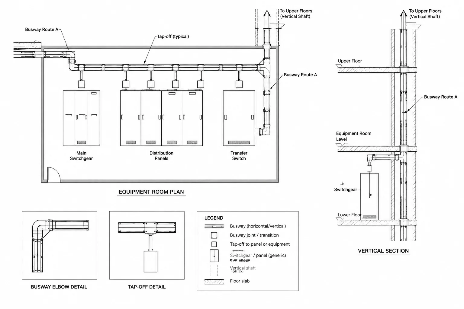
Busway drawings in CAD must connect diagrammatic electrical intent with spatial building coordination. A route that appears complete on a floor plan may still be unclear at a shaft, penetration, tap-off location, elevation change, or equipment interface.
This reference explains how to organize busway plans, risers, enlarged views, symbols, identifiers, and schedules as related parts of the same drawing set. The emphasis is on readable documentation, controlled CAD geometry, and clear separation between design intent and product-specific information that still requires verification.
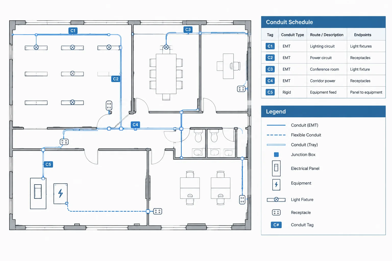
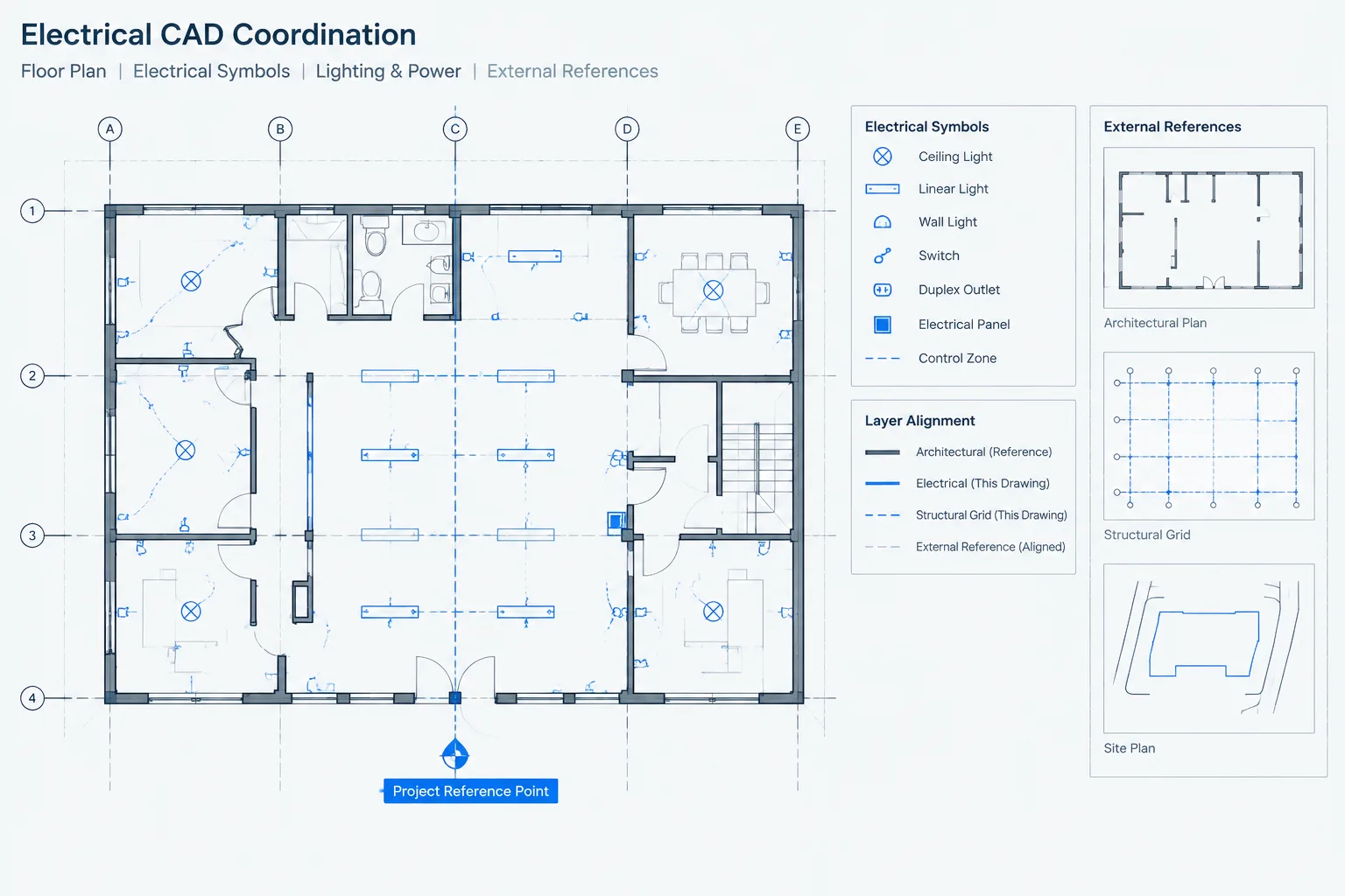
Busway documentation often spans several drawing types. A floor plan may show the route through a building, a riser diagram may explain vertical distribution, and enlarged views may identify tap-off units and equipment connections. If those views are developed independently, route changes and identification errors can quickly spread through the drawing set.
A reliable CAD workflow treats the busway as a coordinated system rather than a single polyline or generic block. The drawings should communicate where it runs, which equipment it connects, how its segments are identified, and where project-specific information must be verified with the selected manufacturer and other disciplines.
What a busway drawing set should communicate
Busway drawings should provide enough information for design coordination without pretending to replace manufacturer fabrication or installation documents. The appropriate level of detail depends on the project stage and drawing purpose, but a coordinated set commonly addresses:
- The general horizontal and vertical route
- Source and destination equipment
- Busway and segment identifiers
- Changes in direction and elevation
- Floor, wall, and shaft penetrations
- Tap-off or plug-in unit locations
- Interfaces with switchboards, transformers, panelboards, and other equipment
- Access requirements and potential maintenance conflicts
- References to risers, sections, schedules, and enlarged plans
- Areas requiring manufacturer or field verification
Do not infer physical dimensions, fitting geometry, support arrangements, or connection requirements from a generic CAD block. These characteristics can vary by product and configuration.
Choose the right drawing view for each question
No single view explains every part of a busway system. Assign each view a clear documentation role and use cross-references to connect them.
| Drawing view | Primary purpose | Typical information |
|---|---|---|
| Floor plan | Coordinate the route with rooms and building systems | Path, equipment endpoints, tap-off positions, penetrations, and callouts |
| Riser diagram | Explain vertical distribution and system relationships | Sources, floors served, segment IDs, tap-off units, and connected equipment |
| Section or elevation | Clarify physical position where plan geometry is insufficient | Relative elevation, structural relationship, access, and crossing conditions |
| Enlarged plan | Resolve congested equipment areas | Connection orientation, nearby equipment, fittings, and interface callouts |
| Schedule | Organize repeated system data | Busway IDs, service descriptions, endpoints, status, and drawing references |
| Detail | Explain a recurring or project-specific condition | Diagrammatic interface, penetration concept, transition, or identification method |
A floor plan should not be overloaded with information that is easier to read in a schedule or riser. Conversely, a riser diagram should not be treated as a scaled routing plan.
Develop a consistent CAD representation
Separate the route from the physical envelope
During early coordination, a centerline can efficiently represent the intended route. As the design develops, selected areas may need an outline or envelope showing the approximate occupied space. Keep these two graphic purposes distinct.
A route centerline communicates continuity and direction. An equipment envelope communicates spatial impact. Placing both on controlled layers allows a drafter to simplify overall plans while displaying additional geometry in equipment rooms, shafts, or other congested areas.
Use blocks for identifiable components
Blocks are useful for recurring components such as elbows, transitions, tap-off units, end conditions, and equipment connection points. Attributes can store an identifier, status, destination, or schedule reference. However, a symbolic block should not be mistaken for verified product geometry.
If a fitting must match a selected busway system, distinguish the manufacturer-coordinated component from the generic planning symbol. A descriptive block name and visible verification note can help prevent conceptual geometry from being reused as fabrication information.
Control layers by information type
A practical layer structure may separate busway routes, envelopes, component symbols, identifiers, hidden or overhead portions, access zones, and reference geometry. The exact naming convention should follow the project CAD standard.
Avoid placing the entire system on one layer. Separate layers make it easier to create discipline overlays, simplified plans, enlarged views, and review plots without deleting geometry.
Identify systems, segments, and tap-off units
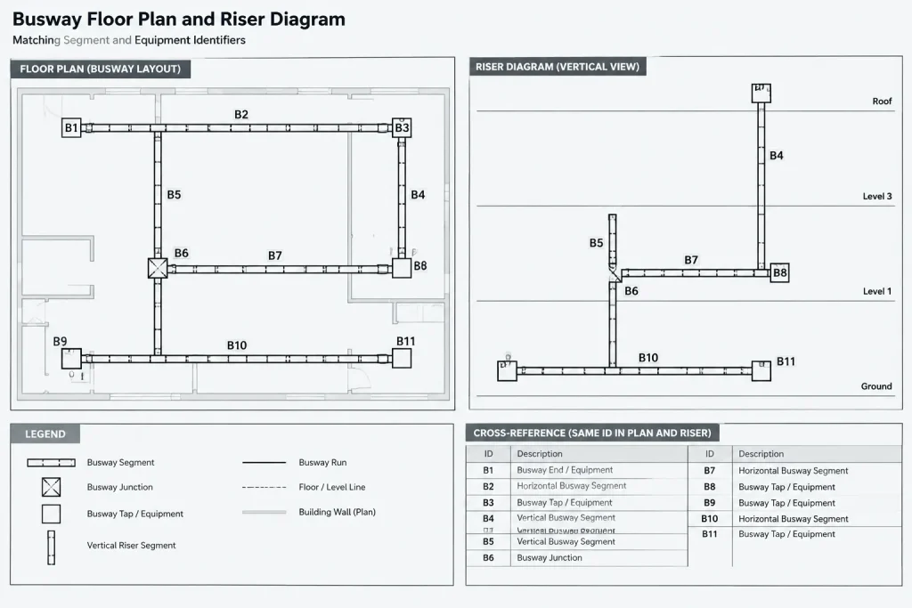
Every repeated item should have a stable identity. A busway may have an overall system designation while individual runs, segments, or tap-off units carry separate identifiers. The naming structure should be understandable without relying only on color, because drawings may be printed in monochrome or viewed with altered layer settings.
Place identifiers close to the represented component, but use leaders when nearby equipment or architectural linework makes ownership ambiguous. The same identifier should appear consistently in relevant plans, risers, schedules, and details.
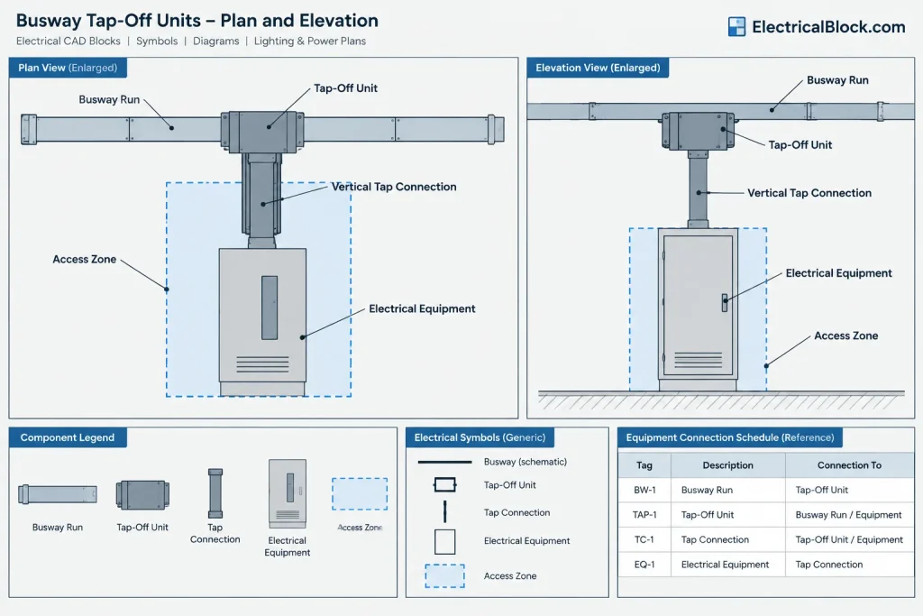
For tap-off units, document the intended relationship rather than implying unverified construction. Useful drawing information may include:
- Tap-off unit identifier
- Connected equipment tag
- Busway system or segment reference
- Approximate plan location
- Associated circuit, feeder, or schedule reference when applicable
- Normal, optional, future, or existing status
- Reference to a detail or manufacturer-coordinated submittal where needed
When several tap-off units are close together, an enlarged plan or elevation is usually clearer than a cluster of overlapping labels.
Coordinate the route in three dimensions
A busway path that appears clear in plan can conflict vertically with beams, ducts, piping, cable tray, ceilings, or access paths. CAD plans should therefore include elevation information wherever the route changes level or passes through a constrained area.
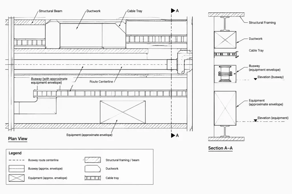
Use one project datum convention consistently. Do not mix references to floor level, ceiling level, and structural elements without clearly stating what each elevation describes. Sections and elevations should identify the same route and segment IDs used on the plan.
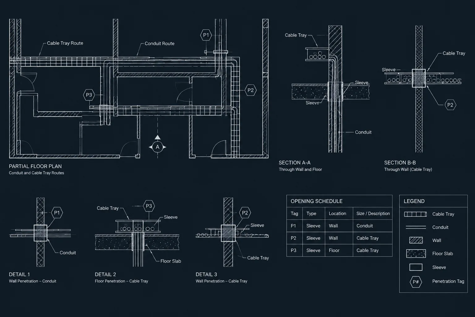
At penetrations, show the relationship between the route and the architectural or structural opening. The electrical drawing can document design intent and an opening reference, while final opening size and edge conditions remain subject to multidisciplinary and product-specific verification.
Coordinate equipment interfaces
The busway endpoint should align with the actual connection region of the equipment, not merely the center of a generic equipment rectangle. Connection orientation may affect equipment placement, fitting selection, access, and the usable routing path.
For each interface, review:
- Equipment tag and orientation
- Incoming or outgoing connection location
- Top, bottom, or side relationship shown by the design documents
- Adjacent working and service areas represented for coordination
- Conflicts with doors, removable panels, or access routes
- Need for an enlarged plan, elevation, or section
- Responsibility boundaries between field work, vendor-supplied components, and other systems
When product information is not final, mark the connection as conceptual and provide a clear verification note. Do not create false precision by drawing a detailed transition based only on an assumed connection point.
Build a compact busway schedule
A schedule can reduce repeated notes and support drawing review. It should organize information already established by the design rather than introduce unsupported technical values.
Useful fields may include the system ID, segment ID, source, destination, area or level served, drawing reference, connected equipment reference, status, and coordination remarks. Additional electrical data should be included only when it has been verified through the project design process.
If schedules are generated from block attributes or external data, establish which source controls. Unmanaged edits to both the schedule and the plan can produce conflicting records.
Plan-to-riser coordination workflow
Trace the complete route. Follow each busway from its source to every endpoint on the plans.
Compare system IDs. Confirm that plan labels, riser labels, and schedule entries use the same designations.
Count identified tap-off units. Reconcile units shown in plan, riser, and schedule views.
Review direction changes. Check that elbows, offsets, and level changes are represented where needed.
Verify equipment interfaces. Compare endpoint orientation with the latest equipment layout and vendor information available to the design team.
Check penetrations and constrained areas. Confirm that referenced sections or enlarged views exist and match the main route.
Review statuses. Ensure existing, new, future, optional, and demolition work cannot be confused.
Common drafting problems
- Using a single untagged line: The route is visible, but its source, destination, and relationship to the riser are unclear.
- Showing every component as exact geometry: Conceptual blocks create false confidence when product dimensions have not been verified.
- Omitting vertical information: The plan looks coordinated while major overhead conflicts remain hidden.
- Moving symbols without updating schedules: Tap-off locations and connected equipment references become inconsistent.
- Relying on color alone: Status and system distinctions disappear in monochrome output.
- Failing to identify responsibility boundaries: Drawings do not distinguish design intent from vendor-coordinated details.
Final review checklist
- Every busway system has a unique and consistently used identifier.
- Routes connect visibly to their intended sources and destinations.
- Plans, risers, schedules, sections, and enlarged views agree.
- Tap-off units are identifiable and associated with the correct equipment.
- Vertical transitions and constrained areas have adequate documentation.
- Generic symbols are not presented as verified product geometry.
- Existing, new, future, and optional conditions are graphically distinct.
- Cross-references point to current drawing locations.
- Notes clearly identify information requiring manufacturer, consultant, or field verification.
Well-organized busway drawings provide a traceable path from system concept to coordinated equipment interfaces. By separating symbolic routing, spatial coordination, identification, and product-specific information, the CAD set remains readable without overstating what has been verified.
Managing busway information across CAD files
Coordination is easier when the project establishes a clear location for each type of busway information. Route geometry, component symbols, equipment backgrounds, annotation, and schedules may be maintained in separate files or controlled through layers and referenced drawings. Whatever structure is selected, the team should know which file controls the route and which views merely display it.
Repeatedly redrawing the same run in unrelated plan, riser, and detail files creates avoidable revision risk. Where the CAD workflow permits, reuse controlled references, block attributes, or coordinated data fields. Diagrammatic risers may still require separate drafting, but their identifiers and endpoints should be checked against the plan source whenever the route changes.
Record the meaning of graphic conventions
A line type, symbol, hatch, or annotation should have a documented meaning. The drawing legend can distinguish route centerlines, approximate envelopes, overhead portions, future work, existing conditions, access zones, and components awaiting verification. These conventions should remain understandable when color is unavailable.
The term bus duct may appear informally in project discussions, while drawings may use busway. Select the project terminology deliberately and avoid switching terms in a way that suggests different systems unless the design documents make that distinction.
Use revision checks that follow system relationships
A route revision is rarely limited to the linework that moved. Review the associated segment label, tap-off callout, elevation note, penetration reference, equipment connection, riser relationship, schedule entry, and enlarged view. This relationship-based review is more reliable than checking only the edited sheet.
Before issue, plot the drawings using the intended output settings. Confirm that identifiers remain legible, hidden or overhead graphics are distinguishable, leaders point to the correct components, and reference backgrounds do not overpower the electrical information.
Define the boundary of the CAD drawing
Busway CAD documentation communicates coordinated design intent; it does not automatically establish fabrication geometry or installation requirements. Generic fittings and equipment interfaces should remain visibly conceptual until verified against current project and manufacturer information.
Where information is unresolved, use a concise verification note tied to the affected component or interface. A targeted note is more useful than a broad disclaimer because it tells reviewers exactly which route condition, fitting, opening, or connection still requires coordination.
Frequently asked questions about busway CAD drawings
What is the difference between a busway plan and a busway riser?
A plan communicates the route in relation to rooms, equipment, penetrations, and other building systems. A riser explains vertical distribution and electrical relationships between sources, segments, tap-off units, levels, and connected equipment. The views should share identifiers, but they do not serve the same drafting purpose.
Should a busway route be drawn as a centerline or an outline?
A centerline is useful for route continuity and early coordination. An outline or approximate envelope can communicate spatial impact in congested areas. The drawing should identify which representation is being used and should not imply verified product dimensions when they are unavailable.
How should tap-off units be represented?
Use a consistent symbol or block with an identifiable relationship to the busway and connected equipment. Attributes may support tags, status, destination, and schedule references. The symbol should remain distinct from manufacturer-verified geometry.
What information should be coordinated after a route change?
Check plans, risers, schedules, sections, elevations, enlarged views, segment identifiers, tap-off locations, penetration references, elevation notes, and equipment endpoints. Also review any background drawings that rely on the former route.
Can a generic busway CAD block define a fitting or connection?
No. A generic block can communicate design intent or reserve a conceptual location, but it should not be treated as confirmed fitting geometry, connection orientation, support information, or fabrication data.
How can busway drawings remain readable in monochrome?
Combine layer control with line types, symbols, text labels, hatches, and status notes. Do not depend on color as the only method for distinguishing systems, conditions, or responsibilities.


Leave a Reply
You must be logged in to post a comment.